Slow Scan RF Spectrum Analyzer using a CATV Tuner
The CATV Television Tuner sold by MTM Scientific, Inc can be used to build a spectrum analyzer for RF. Here we describe a project to scan the frequency range of 473 to 803 MHz. The spectrum analyzer will sweep the frequency range and report measured signal levels using serial port communication. Spectrum analysis of the radio frequency enviroment is especially useful if you are planning to build a radio telescope. By scanning the RF spectrum you can find a quiet part of the RF spectrum, and build a radio telescope which avoids local interference. Note: All kits purchased after 12/2013 include an updated PCB with the trace for this modification already provided... making the project even easier!
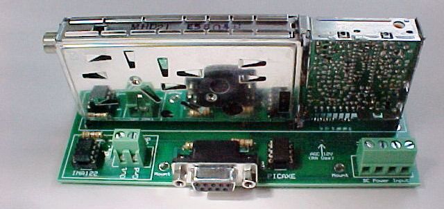
Building this project requires the MTM Scientific, Inc CATV Tuner Motherboard. The Motherboard simplifies wiring connections and also includes a PIC microcontroller and RF detector/amplifier circuit. The PIC controller is a PICAXE-08M. The PICAXE can control the tuner and also communicate with an external computer using the RS-232 serial port interface on the motherboard.
As supplied by MTM Scientific, the CATV Tuner Motherboard Kit has a PICAXE chip pre-programmed for tuning UHF channel 37 for radio astronomy. However the Motherboard also includes a serial port connector, which makes it a simple matter to reprogram the PICAXE for other projects like this one. For the spectrum analyzer project we reprogram the tuner to step through UHF channels 14 to 69 and send the signal level data to a host computer using serial port communication.
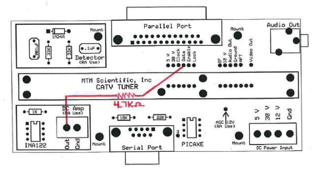
A small wiring change is needed to make this project work with the MTM Tuner Motherboard. This project uses the PICAXE 10 bit analog-to-digital converter to read the signal level. Therefore the output from the DC amplifier must be wired to an input pin on the PICAXE. This is most easily done by wiring a 4.7K Ohm resistor from the DC output to the signal line marked 'data' on the printed circuit board, as shown in the photo.
The code to program the tuner is compact . (The PICAXE chip has only 256 bytes of program memory.) Programming the tuner to a specific channel requires sending a string of 27 bits from the PICAXE to the tuner, as explained in our 27 Bit Tutorial. Because of the limited PICAXE memory, and because the goal is to send a bit stream, the program code is most easily done using binary math with individual bits. This type of programming can be a little bit challenging if you are not familiar with it. You do not need to understand all the details of the software program to do this project, simply reprogram the PICAXE with the code provided below.
The code is designed to send a 27 bit instruction for tuning. The actual tuning frequency is contained in a 15 bit segment of the full string. The code uses binary math to step through the frequencies sequentially using a bitmask. Sending the bit stream to the tuner is done using a technique known as 'bit banging'. Briefly, bit banging is a technique to create a timed series of bits (high and low) that the tuner will accept as a valid program instruction.
Listed at the bottom of this webpage is a link to the program code for the Spectrum Analyzer Project (uhfscan.bas). We have included heavy commenting in the code to facilitate understanding the program flow. The code creates and uses a bit mask to query the status of individual bits in the frequency variable inside an indexed loop.
The program code must be programmed into the PICAXE chip via the serial port. Connect the serial port connector on the Motherboard to the serial port on your computer, a cable may be required. The actual PICAXE programming software is called the "PICAXE Programming Editor" and it is available free at www.picaxe.co.uk Note: We are in the process of switching from the PICAXE-08M to the newer PICAXE-08M2... so look at the chip provided with your kit to determine which one you have when you start the programming portion of this project.
The PICAXE software is powerful and easy to use. The splash screen for the software will ask for confirmation you are programming a PICAXE-08M or PICAXE-08M2 chip running at 4 MHZ. The basic code file we provide can be opened directly, or you can cut and paste the text into the programming editor to create the code from scratch. The actual programming is initiated when you select 'PICAXE' and 'Run' from the top menu. A status bar will show download progress. Note that +5V power must be applied to the Motherboard for programming. There is an extensive HELP file included with the software if you run into problems.
After the chip is programmed with the new code the spectrum analysis program (uhfscan.bas) will run whenever +5V power is applied. The program will output the spectrum analysis data using the same serial port connection that was used for programming. The PICAXE programming software has a serial port monitor under menu selection "PICAXE" and "Terminal". The Terminal will appear as a small window and show the scrolling data text from the serial port. The output from the spectrum analyzer will be a data string with UHF Channel and signal level. Each line of data will contain the UHF channel number (14-69), a blank space, and the signal level at that channel (0-1024 bits). Here is a snippet of the data stream:
34 25
35 66
36 183
37 359
38 256
39 129
40 57
41 32
The numerical data is easily imported into a spreadsheet program (such as Excel) and plotted to create a graphical output. For example, here is the response of the CATV tuner to a sine wave signal centered on 611 MHz.

This simple example only begins to explore the full capabilities of the PICAXE chip and CATV Tuner Motherboard combination. For example the same setup can be used to program the the PICAXE chip to tune any special frequency of interest. Also, no attempt has been made to maximize the speed of the RF spectrum scanning, which would be an interesting area to explore.
Probably the most important innovation in this particular project is using the analog to digital converter on the Motherboard's PICAXE chip to output the data readings on the serial port. This same technique would allow the construction of a stand-alone radio telescope with no external A/D conversion needed, because the data could be sent to a computer via the serial port connection. This is the same idea we use for the PICAXE A/D PICAXE Converter product from MTM Scientific, Inc.
When power is applied to the Tuner Motherboard (+30, +12, +5) the PICAXE chip will begin the spectrum analysis routine. The bandwidth of the IF section of the CATV Tuner is approximately 5 MHZ, which is the width of a standard TV Channel.
The frequency range of the UHF band for channels 14 to 69 is 473 to 803 MHZ. The UHF band is scanned by stepping in 5 MHZ steps. This is equivalent to using a television remote control to step through the channels on-by-one and measuring the signal level.
This project is a great way to start becoming familiar with the CATV Tuner Motherboard and in using the onboard PICAXE chip. The techniques and skills you will learn doing this project have other applications that are only limited by your imagination.
RESOURCE CENTER:
Here is a list of useful resources for experimenting with the tuner...
Program listing of PICAXE code for spectrum scanning: uhfscan.bas
Panasonic data sheet for the CATV Tuner module: tuner.pdf
Data sheet for the tuner's integrated circuit: chip.pdf