Low Cost Analog to Digital Converter Plans
MTM Scientific, Inc.
Collecting and storing experimental data is a common challenge for hobbyists. A popular approach is to use a device for converting analog data into digital data and storing the information on a computer. These devices are called A/D converters: an abbreviation for analog to digital. There is a wide variation in prices for A/D converters and most are expensive. Since hobbyists are usually on a limited budget, we describe here a simple and low cost method to build a basic A/D converter using a single off-the-shelf IC that can be read using a computer's serial port. (In a hurry to get started? You can purchase the A/D chip for this project already programmed and ready to use... see below.)
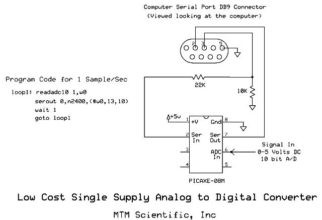
This simple circuit for building an A/D converter uses a PICAXE-08M chip. The PICAXE chip is a microcontroller with numerous useful features, including a 10 bit analog to digital converter. The PICAXE chip also has a serial communication feature which can transmit data directly into a PC's serial port. With only 4 lines of simple computer code (shown below) the microcontroller can be programmed to perform continuous analog to digital conversions and transmit the numerical result once per second. The nonvolatile memory of the PICAXE chip allows the program to be stored indefinitely, and it will recommence whenever 5VDC power is applied.
Wiring diagram for the analog to digital converter project.
Note that this circuit is intended for connection directly to the serial port of a standard PC computer. The circuit diagram shows the serial port connections as you view the connector on the computer. The only additional items required are two resistors and a 5VDC power supply. The 5V supply is for the IC power and it also forms the reference for the analog to digital conversion. As you probably know, 5 VDC is available inside a modern computer... for example at any power connector for adding additional storage drives.
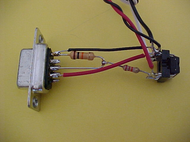
Photograph of the analog to digital converter wired to a serial connector.
This circuit works great with an older PC, in which case you can put together a dedicated data collection system which is also low cost. Serial ports are standard on most computers. The data from the PICAXE can be read by any program capable of monitoring a serial port. The HyperTerminal application works well, and it is included free as an accessory in the Windows operating system. HyperTerminal also allows the data file to be saved. By opening the saved file with Excel spreadsheet software it can plotted to create a graph. Older computers running DOS can monitor the serial port by using a shareware version of the old application ProComm ( Such as version 2.4.3.) Whatever serial communication program you use, it is important to have the communication settings correct: 2400 baud, no parity, 8 data bits and 1 stop bit. Each data sample appears as a new line in the scrolling output. Here is a view of HyperTerminal collecting the data.
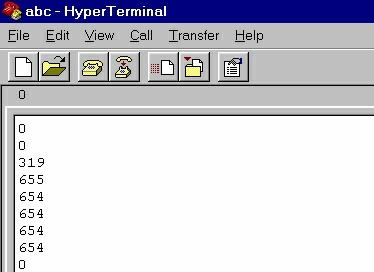
Screen shot of HyperTerminal collecting the data output.
We have written a small program for logging data from the serial port and graphing it on the screen in real time for drift scan radio astronomy. The program logs data from the PICAXE-08M chip every second, averages 60 data points, and plots to the screen once a minute for 24 hours. The program was written and compiled using the Free Basic Programming Language. Here is a screen shot of the program acquiring data, and a link to a zip file which contains the source code, executable code and text file instructions: datalog.zip
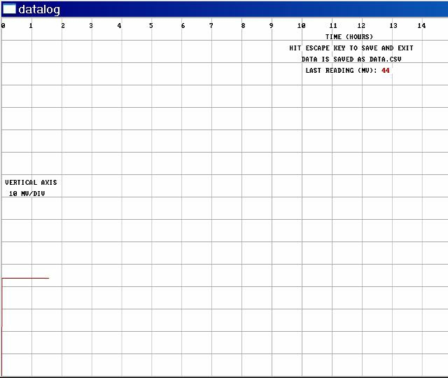
Screen Shot from the serial port data logger program 'datalog' by MTM Scientific, Inc.
The PICAXE chips are available from fellow hobbyist Phil Anderson at his website. He also provides a wealth of additional information for using the chips, including a link to the free software for programming them. The PICAXE chips are programmed using a PC serial port and the same circuit we show here for the A/D converter. By downloading, installing and running the free software you can program a blank chip with the code for this project. The programming software also includes a simple serial port monitor for reading the data as it is received. If you prefer, a chip which has already been programmed can be purchased below.
The data collected by the PICAXE chip is converted with a 10 bit accuracy, equal to 1024 digital steps. The reference for the conversion is the 5 volt DC supply. The resolution of the conversion is therefore 5.0 V / 1024 = 0.00488 volts. The smallest observable signal change you can measure is therefore about 5 mV.
There are multiple options you can explore with this same project. For example the PICAXE chip contains 2 additional A/D converters which can be used to increase your data channels. It is also a simple matter to change the frequency of the data collection. Another possibility is modifying the PICAXE code to convert your data into the units of measure (on the chip) before transmitting the data via the serial port.
This simple project makes it very easy to turn even the oldest computer into a useful data acquisition system.
Click Here to View other Interesting Projects at MTM Scientific, Inc.