Windspeed Indicator Circuit using Inexpensive Diodes
MTM Scientific, Inc
Measuring the speed of the wind is a common challenge for hobbyists. Traditional cup-style anemometers are expensive. Here we present plans for building a simple and inexpensive windspeed indicator circuit using 2 diodes, some standard electrical components and a DC amplifier chip. The accuracy of this device does not compare to commercial anemometers, but the circuit might be useful for detecting a simple 'YES' or 'NO' regards whether the wind is blowing, especially a low windspeeds.
This project is based on a modification of the method known as the hot-wire anemometer. In our case electric power is applied to an ordinary electrical diode, which becomes warm. The diode rises to a steady state temperature in still air. When the wind blows on the diode the temperature drops. The wind speed can be deduced by measuring the diode response and using a calibration chart relating the wind speed to the diode change.
Circuit Diagram Description
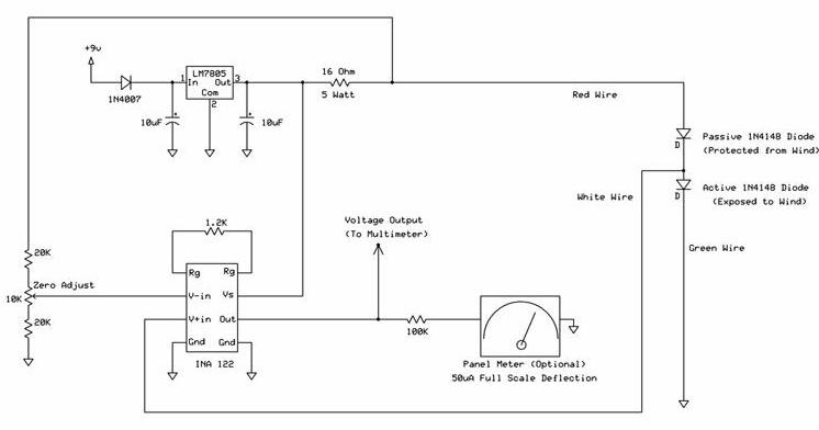
The circuit diagram of the anemometer is shown in Figure 1. The circuit begins with a 9 VDC supply voltage which is regulated down to a constant 5 VDC by the LM7805 voltage regulator. The 5VDC passes through a 16 ohm power resistor to the 2 series-connected 1N4148 diodes mounted in the outdoor probe. The 5 VDC supply routed through the 16 ohm power resistor forms an approximate constant current source supply to the diodes. The electric power dissipated in the diodes causes a rise in both their temperature. Note that while one diode is exposed to the wind the other diode is shielded from the wind. The diode exposed to the wind experiences the cooling effects of the airflow and runs at a cooler temperature compared to the diode protected from the wind inside the probe housing.
The temperature difference of the two diodes in the probe creates a voltage imbalance. The voltage imbalance from the diodes is sent to the amplifier via the white wire. In order to complete the outdoor probe circuit the green wire is connected to ground.
The amplifier monitors the voltage from the probe. The amplifier chip also receives a reference voltage for comparison. The reference voltage is created by the adjustable potentiometer, and trims the 'zero adjust'.
The INA122 amplifier chip is programmed by the feedback resistor to provide a fixed signal gain. In this circuit the feedback resistor is 1200 ohms, which provides a signal gain of 172X.
The output of the amplifier is sent to the panel meter. The purpose of the 100K resistor is to scale the output signal to the range of the meter. The full scale amplifier output of 5V equals the 50uA full scale panel meter range with a 100K resistor. It would also be possible to use a panel meter with a full scale deflection of 5V and eliminate the resistor. Another option is to monitor the circuit output with a digital voltmeter or computer.
Diode Probe Details and Construction
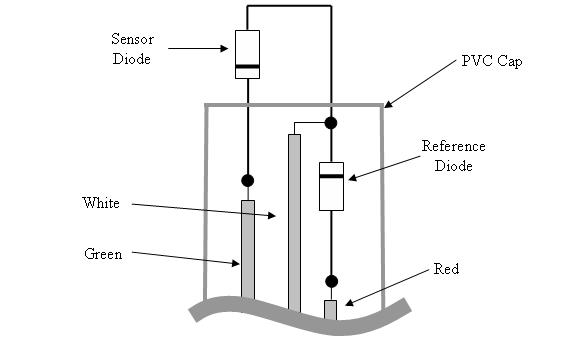
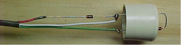
The cutaway view in Figure 2 shows how the probe is wired. Note the color coding of the wires to the sensor which corresponds to the notes on the circuit diagram. Also note the polarity band on the diodes and their orientation.
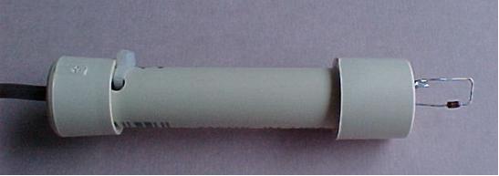
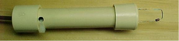
The assembled outdoor wind probe is shown below in Figure 3.
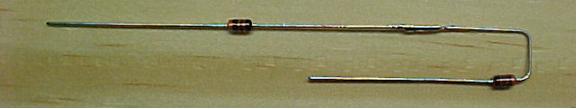
The step-by-step assembly of the outdoor probe is shown in Figure 5. The first step is arranging and soldering the two diodes together. The second step is attaching the wires, after passing the active diode leads through the end cap. The third step is completing the PVC pipe enclosure and bottom end cap. Note how the wires leading to the probe are secured to the plastic housing using a cable tie, as shown. The cable tie acts as a strain relief to prevent dislodging the sensor diodes by pulling on the wires. It is important to take care that the wires do not touch together and short inside the probe housing.
Project Parts List
Here are the parts required to build this project according to these plans.
Jameco Parts:
Diode 1N4148 (Part 36038CK), Panel Meter 0-50uA (Part 315301), Heatsink (Part 326596CK), Connector 3 Terminal (Part 99398), Connector 2 Terminal (Part 99427), Resistor 100K (Part 691340), Resistor 1.2K (Part 690881), Resistor 20K (Part 691171), Potentiometer 10K (Part 254677), Diode 1N4007 (Part 36011), Capacitor 10uF (Part 330799), Power Resistor 16 ohm (Part 660421)
Digi-Key Parts
Micro-Power Instrumentation Amplifier (Part INA126PA-ND)
Miscellaneous Parts
3 Strand Solid Copper Wire (Color Coded Red, Green, White), 1/2 PVC Pipe (3 inch), 1/2 PVC Cap, Circuit Board or Experimenter Board, Cable Ties, 9VDC Power Supply
Circuit Assembly
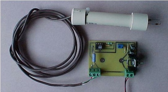
The Wind Speed Circuit can be built on ordinary experimenter type circuit board. During the development of this circuit we created a custom circuit board with some additional useful features, as shown in Figure 6.
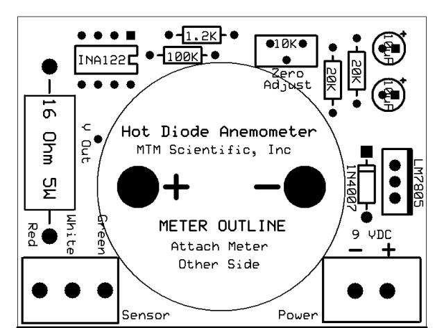
The component layout for the circuit board we built is shown in Figure 7.
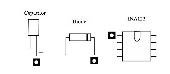
The electronic circuit board was assembled by installing the components and soldering them in place. Some of the electrical components must be inserted into the circuit board a specific way. The components are: 1) the LM7805 voltage regulator, 2) the 1N007 diode, 3) the 10uF capacitors, and 4) the INA122 IC. Notice that some of the solder pads are square in shape, to aid proper insertion and assembly.
Testing and Installing the Indicator
You can begin testing the indicator and probe on your benchtop before installing the probe outdoors. The power supply for the circuit can be any +9VDC source with a current output capability of 0.25 amps minimum. A power supply greater than 9VDC should not be used because the voltage regulator on the circuit board will become too hot. The input on the circuit board is diode protected to prevent damage if the power leads are connected in reverse. Pay attention to the '+' and '-' labels on the circuit board.
The wind speed circuit must be adjusted before it can be used to measure wind speed. The circuit is adjusted using the 'zero adjust' trimpot. The trimpot is the blue rectangular component on the circuit board with a small screwdriver slot for adjustment. Before making the adjustment connect the probe to the circuit board. Mount the probe vertically in a calm area with no air drafts. Apply power and wait 5 minutes for the probe to warm up. Monitor the voltage output with a digital multimeter. The trimpot is adjusted while watching the voltage output. Trim the output to about 1 volt to start. Then slowly adjust the trimpot lower until the output voltage is 0.10 volts. The trimming procedure balances the circuit for detecting the probe signal.
It is very important to protect the probe from air drafts when making this adjustment. In a pinch you can cover the probe with a styrofoam cup to shield it. However, do not allow the cup to touch the diode probe. You will find the probe is very sensitive to airflow. For example, waving your hand near the probe will create enough of an air movement to affect the signal.
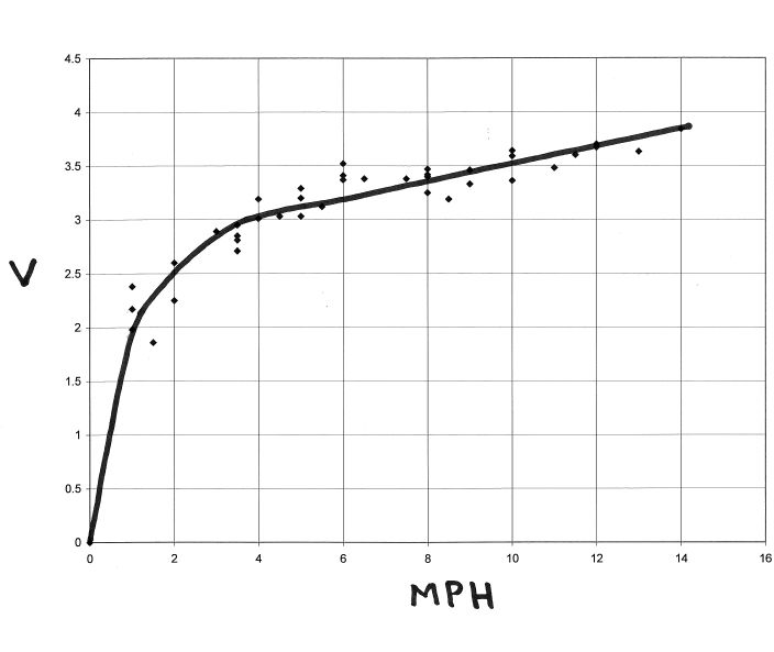
The output of the indicator is a voltage that ranges between 0.0 and 5.0 volts. The voltage output is available from the amplifier IC. The relationship between the voltage output and the windspeed is shown in Figure 9. The relationship between the voltage and windspeed is not linear. The sensor is more sensitive at low windspeed, therefore the voltage change is greater at slow windspeeds. At higher windspeeds the probe becomes less sensitive and the voltage output change is less.
The voltage output from the circuit board can be measured using a digital multimeter. This method is suitable for making occasional measurements of windspeed. Many experimenters will be interested in monitoring the output with a computer. There are many analog to digital devices available for this purpose. We have published a simple circuit for building an extremely low cost A/D converter using one IC on another webpage.
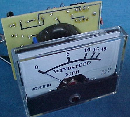
The output of the windspeed circuit can also be connected directly to an analog meter. The circuit board we build was designed for mounting directly to a small meter with 50uA full scall meter deflection, such as Jameco Electronics Part # 315301CK. Mounting the circuit board to a meter makes for a compact and easy-to-read indicator. A custom scale was added to the meter which will allow readings directly in miles per hour (MPH), as shown in Figure 10.
Using the Indicator
There are some limitations on the use of this circuit. Most notably we have found that rain and snow affect the readings. Therefore you may want to consider mounting the probe in a location that has some shelter from above. Also, we found that there was some variability in the output signal for the different probes we built. Ultimately we decided this circuit was useful and interesting, but was not a good candidate for a kit that would perform as a calibrated sensor when built from scratch. This circuit might be especially useful if you would like to turn a device ON or OFF based on whether the wind is blowing.
Ideas and Things to Try
The windspeed probe can be used to evaluate different sites at your location for wind availability. For example, a common question relates to high tall the wind tower should be. This question can be explored by mounting the probe at different heights to measure the difference. A similar set of measurements can be made to evaluate different locations around your site.
Data logging equipment makes wind resource evaluation easier. You might consider purchasing a simple data acquisition port for your computer. An inexpensive starter system is available from Dataq Instruments for about $25. The data logger includes the software to make your computer acquire the data in a strip chart format, which is very convenient. Visit Dataq at http://www.dataq.com
It's also possible to build your own data acquisition system. For example, you can use a PICAXE chip to create a very simple A/D converter. The chip has the ability to sense the voltage, convert it to a number, and send the number into the standard serial port on your computer. Here is a link to a circuit for making the analog to digital converter. This simple circuit will send the data into a computer serial port once per second. The data can be read using a serial communication application, such as Hyperterminal.
References
There is a very good website from an experimenter in Sweden that has experimented with and published additional information about this type of air flow sensor. It is here:
http://www.fonema.se/anemom/anemom.html