This
simple hardware Random Number Generator
(RNG) project is designed to create a continuous string of
completely random numbers. The
numbers are generated from the random noise of a reverse-biased
semiconductor junction in a transistor. The basic unit of numerical
output from the RNG is a continuous string of random bits
(e.g. "1" or
"0"). The individual bits can be combined to create any other type of
output... such as
numbers, text strings, passwords or ASCII symbols.
Generating truly random numbers is surprisingly difficult to do. Stated another way, generating numbers without any traces of a repeating or predictable pattern is very challenging. Computers are notoriously bad at generating random numbers. Which makes sense: Computers predictably perform the instructions they are given to generate numerical output. Hardware Random Number Generators take a different approach to generating random numbers. The RNG begins with a physical process that is intrinsically random. The physical output of the random process is then used to generate the random numbers.
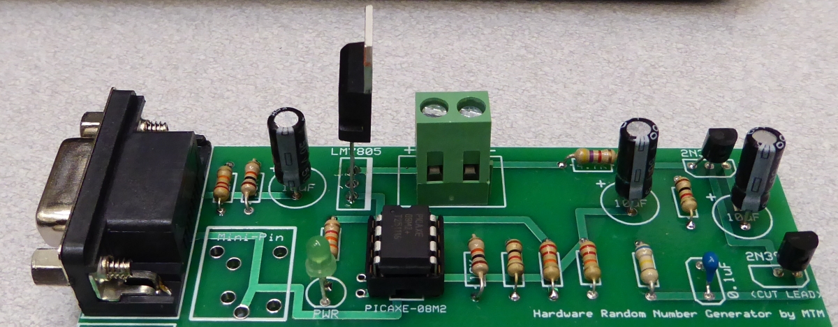
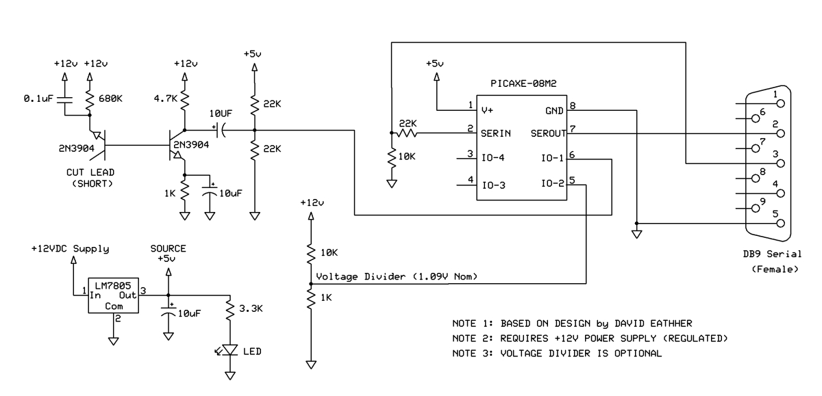
In this RNG the random physical process is the electrical noise generated in the reverse-biased semiconductor junction of a 2N3904 transistor. The 12V reverse bias was carefully chosen to generate sufficient noise, but not to damage the transistor. The noise from the transistor is amplified by a second transistor. The signal from the second transistor is capacitively coupled to a resistive voltage divider. The result is an analog noise signal approximately centered at a level of 2.5V as shown in the oscilloscope trace in Figure 3.
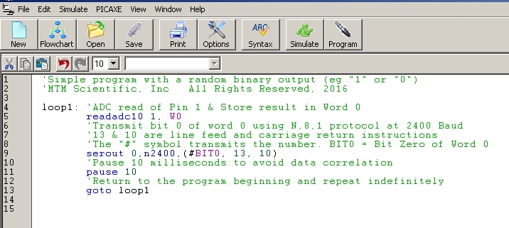
The noise voltage from the transistor circuit is converted to a number using an analog to digital converter. After conversion, the numerical result is serially transmitted to a host computer. The conversion and transmission are both easily implemented by using a PICAXE-08M2 microcontroller. The PICAXE-08M2 is essentially a small computer on a chip. The PICAXE is programmed using a simple computer language called 'Picaxe BASIC'. A sample program listing is shown in Figure 4.
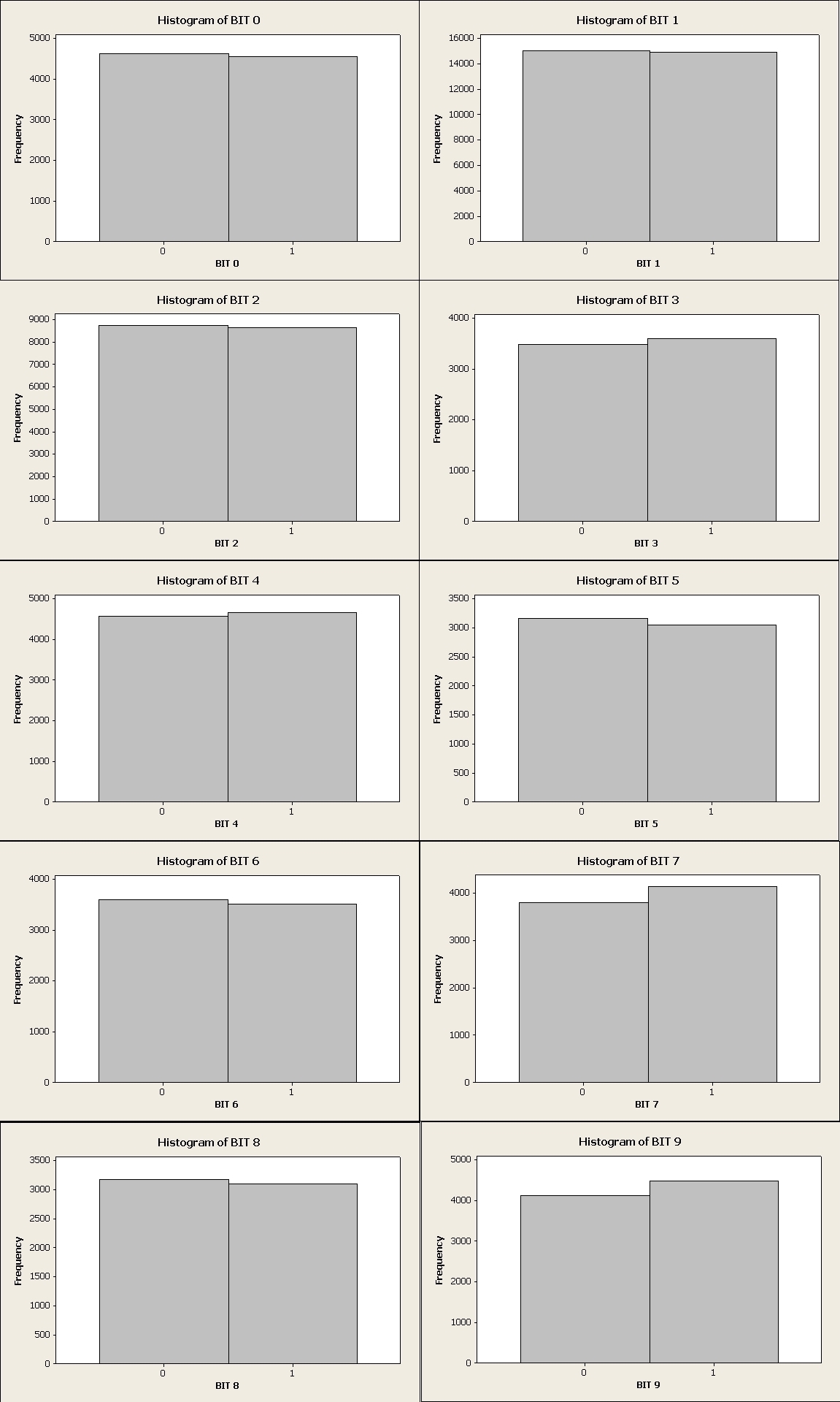
The analog to digital (ADC) conversion generates a binary number 10 bits wide. But not all 10 bits have the same degree of randomness, as shown in Figure 5. We chose to only use the least significant bit of the conversion. The least significant bit represents a voltage change of only about 5 millivolts (0.005 Volts). The bit with the lowest amount of randomness is the most significant bit of the ADC conversion, which makes sense. In the program listing you will notice that a time delay was introduced between ADC readings. This was done to prevent correlation between consecutive readings.
The string of bits from the ADC conversion can be combined to create other types of random output. For example, by combining 8 bits together we can create a byte (Numerical range 0-255). A byte can also represent an ASCII character, per the standard encoding table. The data output conversions can be programmed using simple Picaxe BASIC commands in the PICAXE microcontroller, before the data is serially transmitted. The randomness of the output can be tested using special tests created for the purpose. For example, the 'DIEHARD' suite of tests written by George Marsaglia.
You can build the hardware random number generator using the information we have presented here. Advanced experimenters may have an interest in additional details about the project. We have collected some of the additional project information in a documentation file. The information is provided in electronic format as a zip file. The additional information includes an instruction manual, parts list, PCB files, more Picaxe Basic programs and information for doing the 'DIEHARD' randomness tests. Here is a link to the information.
Hardware Random Number Generator Zip File (10 MB)