How to
Build an AM Transistor Radio
M. Mruzek,
Michigan USA
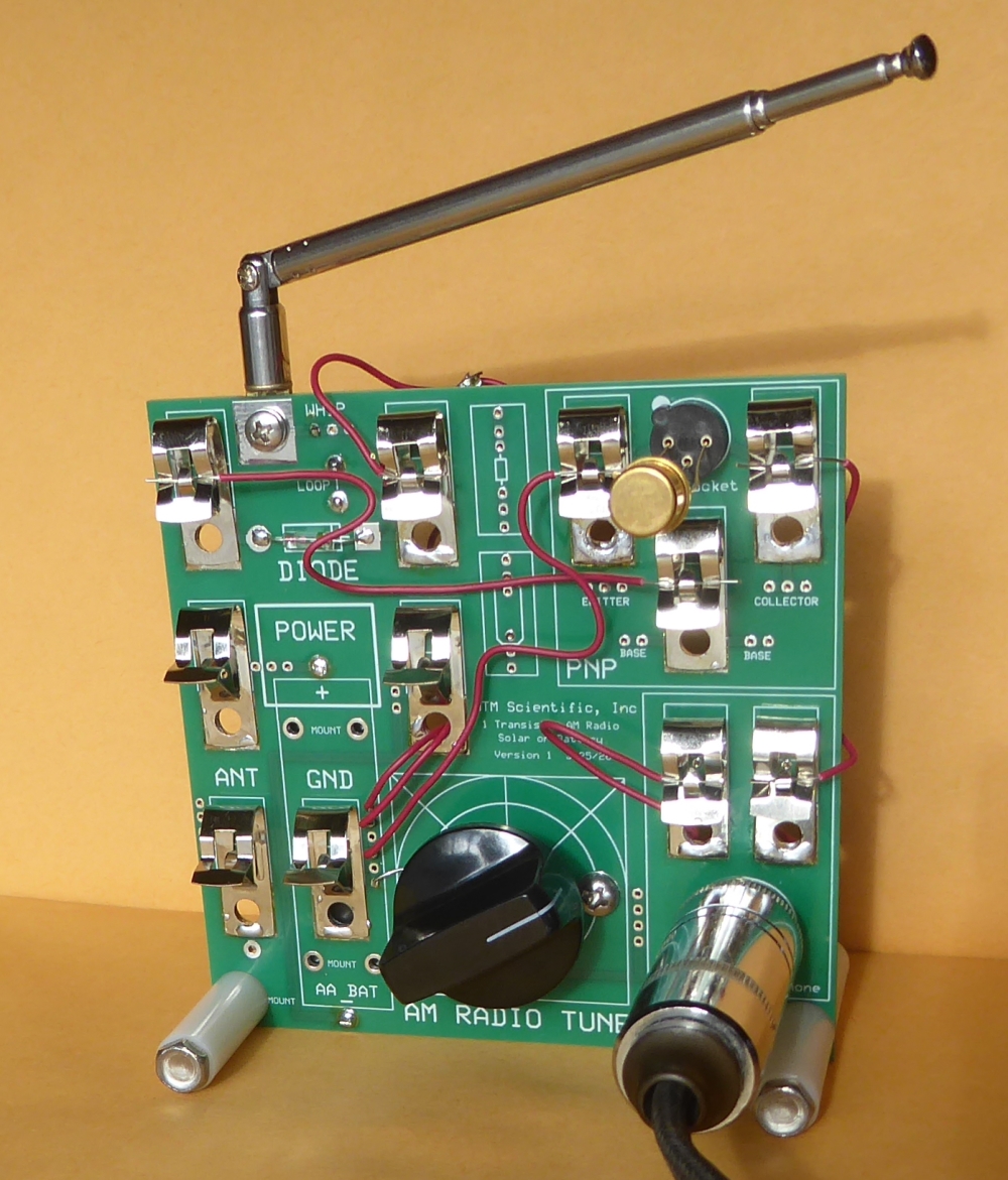
Figure
1: Homebuilt AM Transistor Radio
This page describes building a vintage one transistor AM
radio. This radio tunes the AM broadcast band from
approximately 550 KHz to 1600 KHz. This project is based on
plans originally published in 1955 for a solar-assisted AM
radio using a B2M sun battery from International Rectifier
Corporation.
The electrical schematic for the AM radio is shown in Figure
2. The main components of the radio are (from left to right):
A loopstick antenna "L" with whip "A", air variable capacitor
"C", point-contact diode "D", germanium PNP transistor "V",
sun battery "PC" and high impedance headphones.
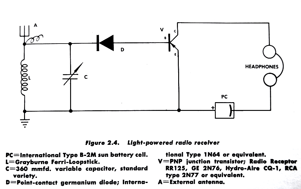 Figure
2: Electrical Circuit for the AM Transistor Radio
Figure
2: Electrical Circuit for the AM Transistor Radio
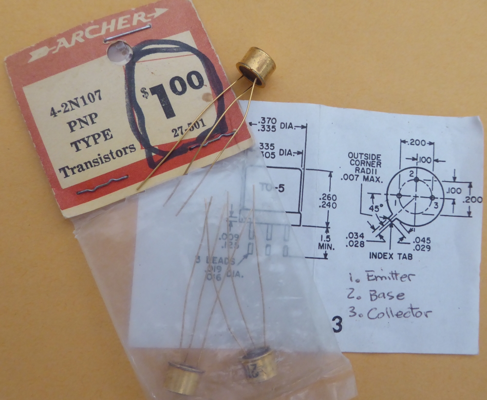
Figure 3: Germanium
PNP Transistors from Archer
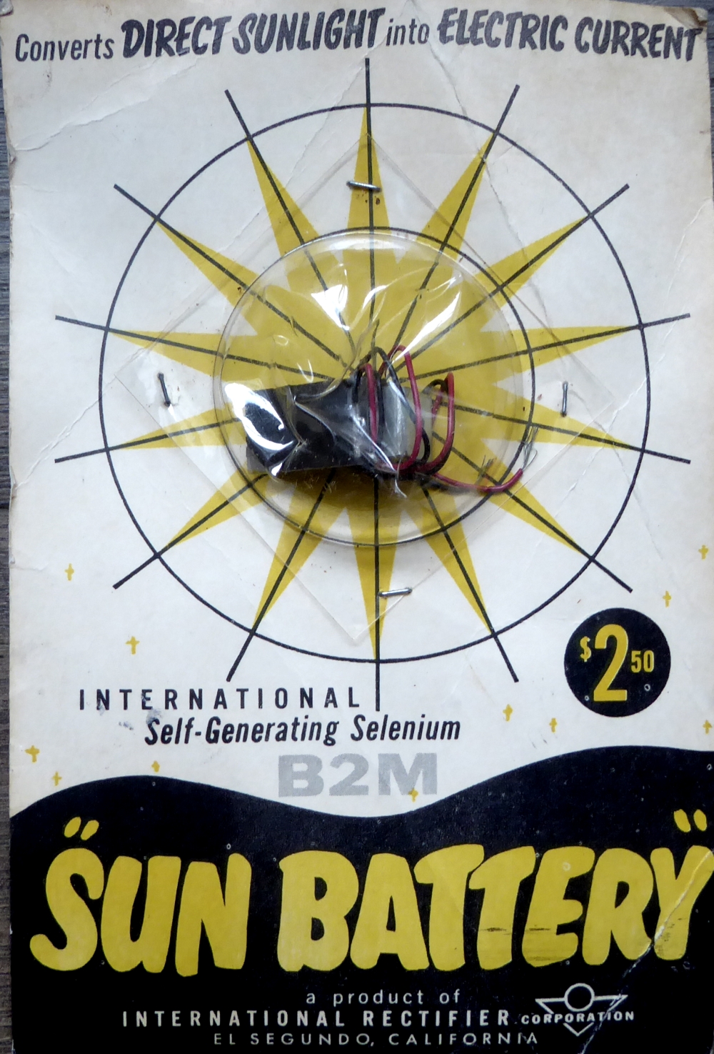
Figure
4: The B-2M Sun Battery
The ferrite loopstick antenna was a staple of early portable
AM radio designs. Loopsticks consist of fine wire wound over a
phenolic tube, with a ferrite core center. These antennas were
a popular compact alternative to the long wire antennas used
by most crystal sets. We were able to find the exact loopstick
part called out in the instructions. The instruction sheet
included inside the package is shown in Figure 5.
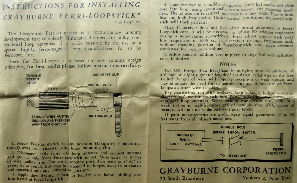
Figure 5: Instructions
for the Grayburne Ferri-Loopstick Antenna
The air variable capacitor for this project is the same type
we have been selling at MTM for other projects, including the
Shortwave Radio Kit and AM Loop Antenna. The capacitor
is shown in Figure 6. The capacitor is front-face mounted to
the PCB using short #6-32 screws. Exercise care with the
screws! If they are too long the capacitor plates will be
damaged.
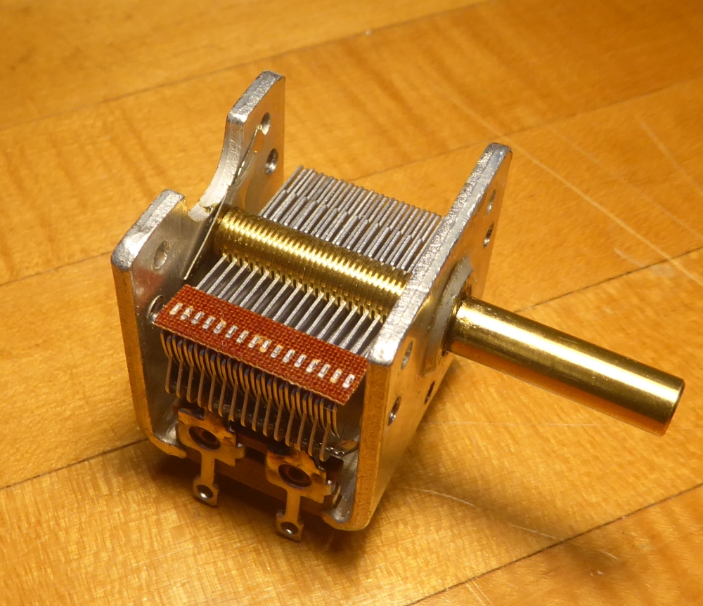
Figure 6: Air Variable
Capacitor
The headphones for this project need to be high impedance
type. (Most modern day headphones are low impedance.) The high
impedance headphones shown in Figure 7 were purchased at a
hamradio swap meet. Similar headphones can be found on auction
sites, such as EBAY. Our headphones have an impedance of
about 2000 ohms, as measured with a multimeter. These
headphones have a standard 1/4" monaural plug, although pin
type terminals will also work, since we have Fahnestock clips
available.
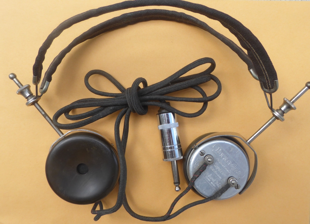
Figure 7: High
Impedance Headphones
We used a single 1N34A point-contact germanium diode for the
detector in the AM Radio circuit. These diodes are still
fairly easy to source. Figure 8 is a photo showing why these
diodes are called point-contact. Close inpection reveals there
are actual points which contact the germanium elements. This
is amazingly similar to a Cat's Whisker used with a piece of
Galena in crystal sets.
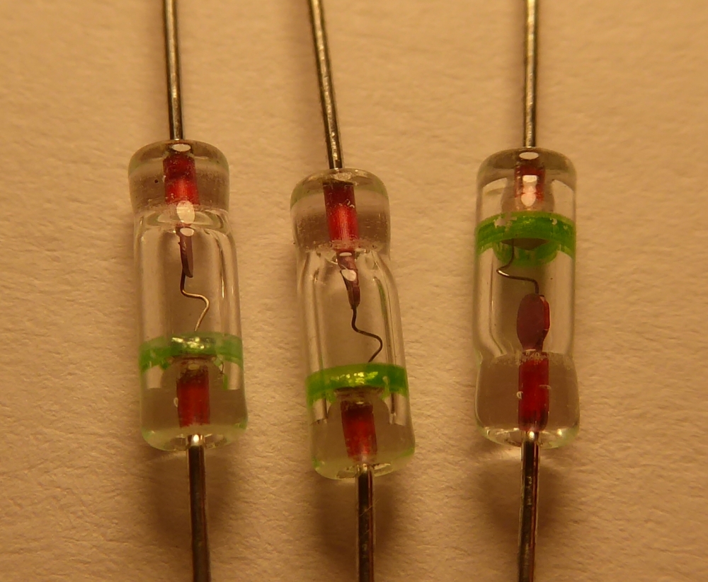
Figure
8: 1N34A Point Contact Germanium Diodes
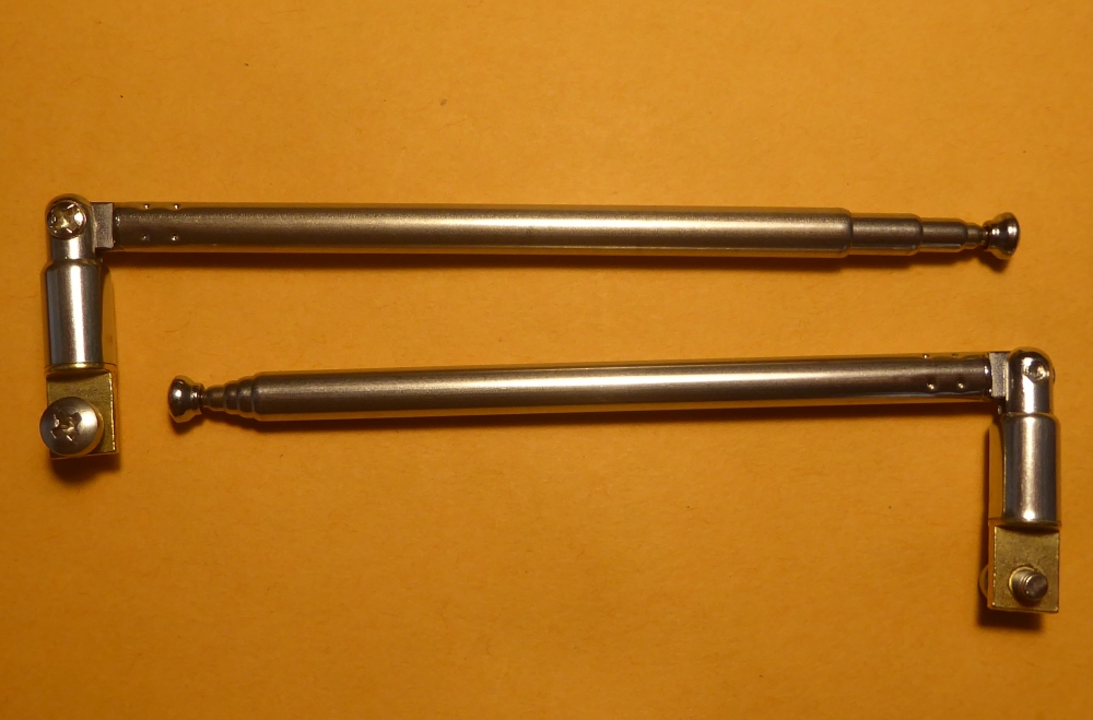
The AM Radio plans call for a short external antenna. We used
a simple whip antenna, as shown in Figure 9. This antenna can
be attached to the printed circuit board with a short metric
M3 screw. The antenna can be soldered in place for an
extra-secure connection. We sourced these antennas from EBAY.
Figure 9: Short Whip Antennas
The AM Radio can be wired together using just about any
breadboard configuration imaginable. We decided to create a
printed circuit board (PCB) for the purpose. We endeavored to
keep the board smaller than 100mm square, such that we could
purchase 5 boards for $5 from PCBWAY.COM The free design
software we used to create the boards is from
ExpressPCB.COM. The front and back of the AM Radio PCB
boards are shown in Figure 10.
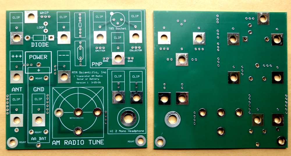
Figure 10: Printed Circuit Board for the
AM Radio
The original plans called for using a solar battery. We chose
to provide an alternative source of power by using a single AA
battery. We were able to source from Digikey a very well made
metallic battery holder, which is shown in Figure 11. The
battery holder is soldered to the PCB using the tabs.
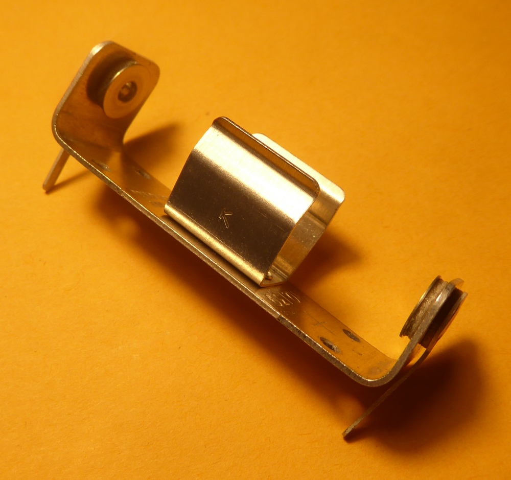
Figure 11: AA Battery Holder for PCB
Mounting
The circuit board was designed to incorporate mounting feet,
such that the PCB would stand upright on its own. The mounting
parts are shown in Figure 12. The mounting feet consist of 2
threaded nylon spacers used with an extra-long #10-32 screw.
These parts are available from Digikey.
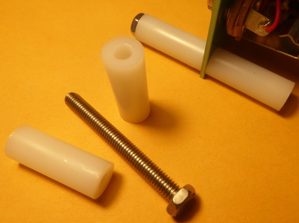
Figure 12: Mounting Hardware for the PCB
feet
The PCB was designed to make liberal use of Fahnestock clips.
These classic clips were previously a mainstay of the homebrew
radio experimenter. The clips allow simple and flexible
circuit wiring using ordinary solid copper wire. We generally
use 22 gauge. These clips were purchased from AMAZON.COM We
placed custom solder pads on the PCB for the clips, such that
they can be attached with careful soldering. The clips can
easily be soldered in place if they are pre-tinned on the
backside before placement.
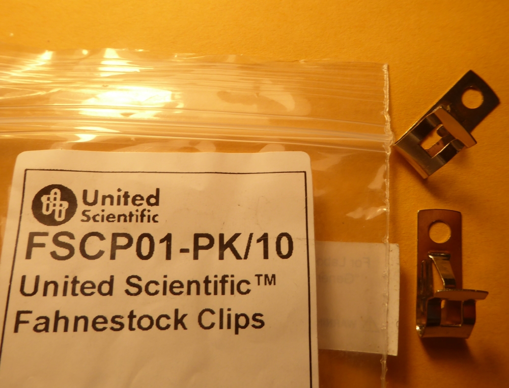
Figure 13: Fahnestock Clips
Mounting the loopstick antenna was a challenge. We wanted the
antenna to be behind the PCB and in free space, away from
other components. The loopstick has a small mounting bracket
already. Therefore a single tab terminal was mounted to the
PCB via a pair of solder plated holes. The tab and mounting
details are shown in Figure 14. These tabs are available from
Digikey. We drilled out the hole in the tab for a #6-32
stainless steel screw with nut.
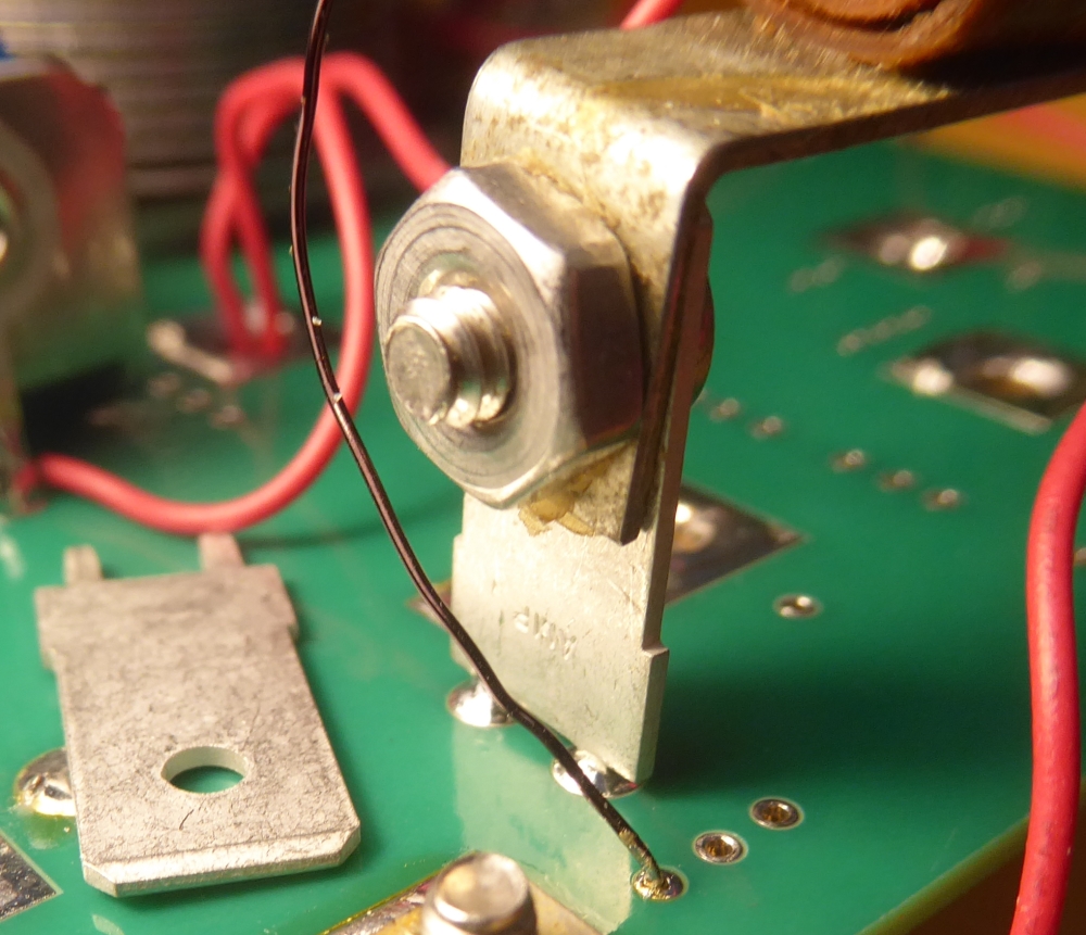
Figure 14. Solder tab and mounting
details for the Loopstick
The germanium transistor is mounted in a metal can type of
case. This classic case style is called TO-5. To our great
surprise we found that Digikey still sells a through hole
socket for mounting these devices. The socket and
transistor are shown in Figure 15. Note that the transistor
and socket have a marking tab for proper alignment of emitter,
base and collector.
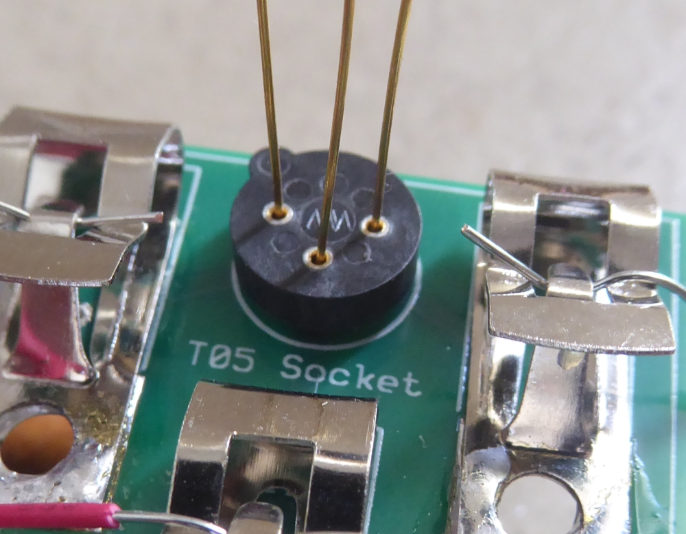
Figure 15: Mounting Socket for TO-5
Transistor
The typical maximum hole size allowed in standard PCBs is
about 1/4 inch. Mounting the variable capacitor and phone plug
socket required larger holes. We found that enlarging the
holes was easily done by using a step drill, as shown in
Figure 16. This particular bit was purchased at Harbor Freight
for about $5. A clean drill hole can best be made by clamping
the PCB to a piece of wood as a backstop.
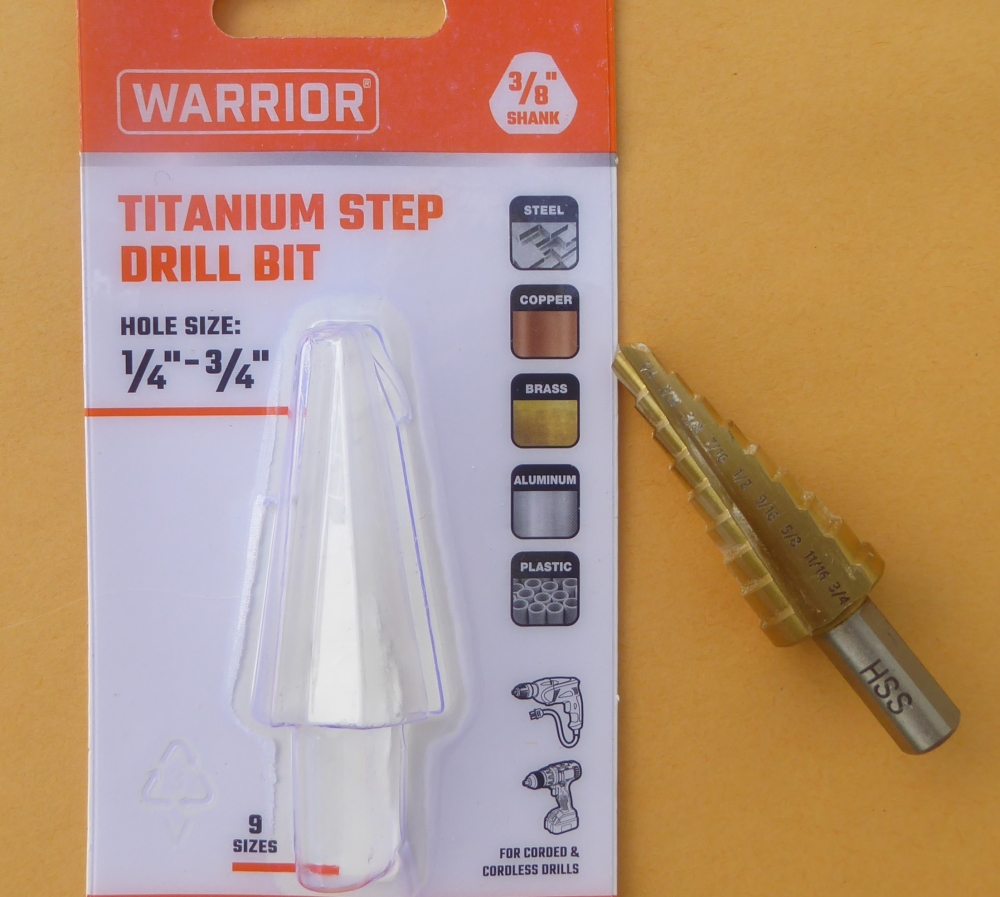
Figure 16: Step Drill for Enlarging PCB
Holes
The radio was fairly easy to assemble. We prefer to use
vintage lead/tin solder for projects like this. It is
important to use solder with a non-corrosive flux. (Plumbing
solder has a corrosive flux that will eventually cause
damage.) Keep the tip of your soldering iron clean with a damp
sponge. Wire strippers are a great convenience for preparing
the copper wire connections. Here are a few photos of the
assembled radio.
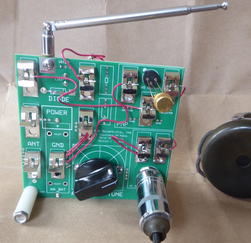
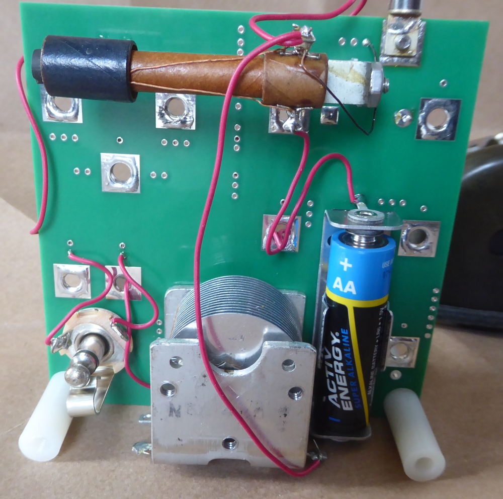
Figures 17 & 18: Front and Back of
the AM Radio
The wiring routing for the radio is not critical. The numerous
holes in the PCB are useful for passing between front and
back. You may have noticed that we placed outlines for a
resistor and capacitor on the PCB. This was included as a
convenience for future experimenting, as some radio circuits
call for biasing the transistor, or adding capacitance.
Frankly, we were quite surprised at how well this radio works!
The tuning is sharp, and the sensitivity is reasonable, even
using only the whip antenna. We expect the performance would
be even better with an external long wire antenna and a solid
earth ground.
Here is a parts list for the AM Radio Project. You may have
some of these items in your junk box already. Many items have
substitutes, such as the NPN germanium transistor.
Here is a part's list for the AM Radio Project:
Printed Circuit Board, PCBWAY, Qty: 1
Air Variable Capacitor, MTM, Qty: 1
High Impedance Headphones, EBAY, Qty: 1
Loopstick Antenna, EBAY, Qty: 1
Round Standoff, Digikey, 145-15TSP025-ND, Digikey, Qty: 4
Mono Connector Jack, Digikey, SC1085-ND, Qty: 1
PCB Mounting Tab, Digikey, A131043-ND, Qty: 1
TO-5 Transistor Socket, Digikey, ED11270-ND, Qty: 1
AA Battery Holder, Digikey, 36-2222-ND, Qty: 1
Phenolic Knob, Digikey, 1722-1125-ND, Qty: 1
Solid 22 Gauge Wire, 839-30-02092-DS-ND,Digikey, Qty: 2 feet
Fahnestock Clips, Amazon, Qty: 11
Whip Antenna, EBAY, Qty: 1
Loopstick Antenna, EBAY, Qty: 1
Germanium PNP Transistor, EBAY, Qty: 1
Here is a link to the PCB Gerber files in a Zip: PCB Gerber Files
Here is a link to the original PCB design file, created using
ExpressPCB software: PCB Design
File