MTM Scientific, Inc... Solar Tracker Information
Version Francaise: Courtesy of Gerard JOUAN
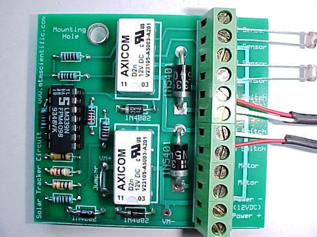
On this private customer webpage you will find additional information about building Solar Trackers, with some color photographs to aid your assembly of the kit. Here is a view of the Solar Tracker 2 Kit (#ST2) assembled and in use.
Assembled View of the Standard Solar Tracker Circuit Kit (#ST2)
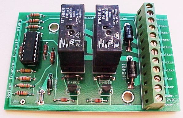
Assembled View of the Heavy Duty Solar Tracker
Circuit Kit (#ST2HD)
The new Solar Tracker Kit #ST2 was designed with many useful additional features. One of the most useful is the smaller size, which allows it to be mounted inside a standard outdoor junction box as shown here.
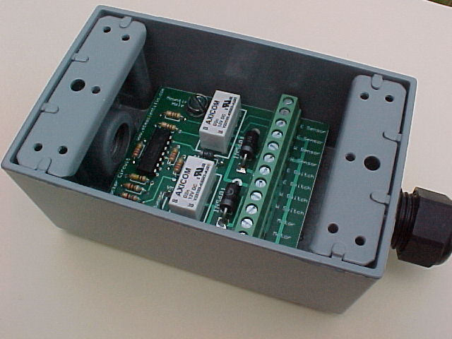
The small size of the #ST2 allows it to fit inside a standard outdoor junction box.
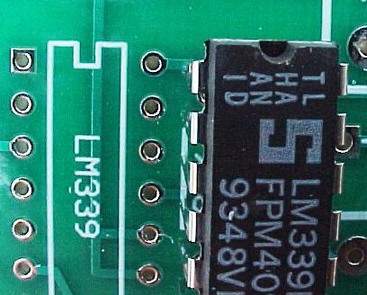
Install the LM339 Comparator with the top notch aligned to the artwork outline.
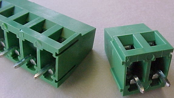
Note that the Terminal Blocks will mate together using the side-slides. Lock together before soldering.
Frequently Asked Questions (FAQ's)
I'm bench testing my Solar Tracker Kit and the motor only moves one way (EAST)? Your kit is working properly. Remember that the circuit has a feature to reset your tracker to the East at the end of the day. The low light level on your bench has the circuit trying to do the reset to the East. Solution: Do the testing outdoors in bright sunlight, or use the diagnostic bench setup described below.
I'm bench testing my Solar Tracker Kit and I can hear the relay clicks, but the motor does not move? Your kit is working properly. For the motor to move the limit switches must be installed. The motor power path is through the normally closed limit switches. Solution: Install the limit switches, or jumper out the limit switch connections on your board. (See diagnostic bench setup described below.)
I was testing my Solar Tracker kit and the 339 comparator IC got hot and smoked? The comparator was damaged by static electricity or a voltage surge from your power supply. Solution: Replace the comparator with a LM339 IC that's available from Radio Shack for about $2 (Part #276-1712).
I'm testing my Solar Tracker kit, but the motor is moving my tracker the wrong way? Your kit is working properly, but the East and West directions are reversed. Solution: Reverse the wiring of the two leads to the DC motor.
I've replaced a photocell on my tracker (with one purchased locally) and now my tracker does not work? The photocells supplied with the MTM kits are special, and have been selected for a specific resistance range and then individually matched for equal performance. Repair your unit by purchasing the replacement photocells available from MTM Scientific on the Solar Tracker webpage.
My Solar Tracker has worked well for some time now, but suddenly has stopped tracking. What's wrong? First, check the voltage level of your battery. Second, check the resistance of your photocells in bright sunlight: They should read 65 ohms or less. After that, the most common problem after long term use is from the mechanical relay contacts wearing out from switching of the inductive motor load, especially with large motors and big tracker payloads. Motors are demanding electrical loads which create arcing on the contacts. Relay life can be significantly extended by installing a snubber resistor across the leads of the motor... for 12V systems a 100 ohm power resistor is reasonable. (Radio Shack #271-135). The Heavy Duty Kit is better for large trackers, and has relays which can be replaced.
I am using a Linear Actuator that already has limit switches. What should I do with the limit switches provided with the kit? You should use both. The actuator limit switches protect the actuator. The tracker limit switches protect the tracker. Arrange the tracker limit switches to actuate BEFORE the limit switches on the actuator. If the tracker limit switches should fail you will still have a protected actuator.
I'm experimenting with different tracker designs and circuits... are the circuit diagrams for MTM Solar Trackers available for puchase? Yes, the circuit diagrams for all the MTM kits (Regular, Heavy Duty and PICAXE) are contained in our E-Booklet for $15. The E-Booklet also has additional information about tracker design and includes more photographs of solar tracker projects.
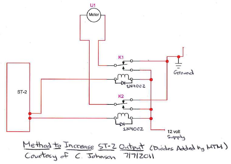
Is there an easy way to increase the current output of the kit for a really large motor? The standard Solar Tracker Kit (#ST2) will handle up to 3 amps, and our Heavy Duty Solar Tracker Kit (#ST2HD) will handle up to 8 Amps. Recently a customer sent us this circuit diagram, which shows a very clever method for adding 2 external relays (K1 and K2) to increase the current capacity. We've added 2 diodes to snub the inductive spike from the relay coils. Note: Dark Reset does not work with this circuit.
Kit Assembly Troubleshooting
We have sold over 1000's of these kits without problems. However, If you are having trouble with your kit, here is a list of the most common problems we have encountered working with customers:
1) Forgetting to install the power supply jumper on the circuit board.
2) Solder Problems (Incomplete solder joint, or solder shorting between pins... especially in the critical area around the IC comparator socket.)
3) Resistors placed in the wrong location, or diodes installed backwards.
4) The Integrated Circuit Chip is installed backwards. (Lethal to the IC) The IC can also be damaged by static electricity.
5) A wire inserted into one of the screw connectors that is not making contact or is loose. This problem happens surprisingly often, so look close!
Bench Testing the Assembled Kit
Here is the procedure we use to verify correct assembly and operation of solar tracker kits. You may find this procedure useful if your solar tracker project is experiencing problems, and you would like to test the solar tracker kit assembly separately. Begin by installing 2 resistors of 150 ohms resistance in the sensor connectors. Also install 2 shorting jumpers across the limit switch connectors. Provide a solid 12VDC power supply of known polarity and quality, such as a car battery or bench top power supply.
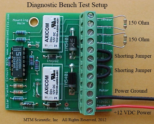
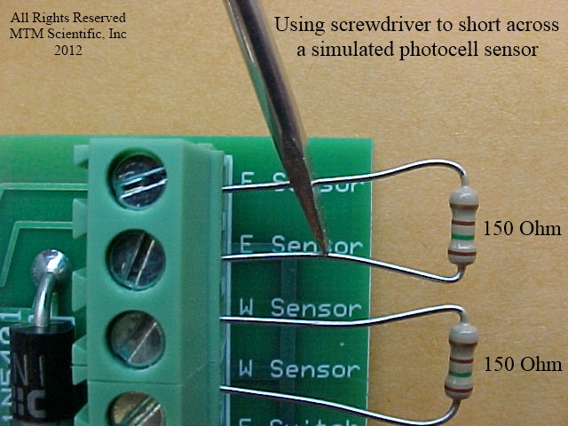
Next, using the tip of a screwdriver, short across one of the resistors. You will hear the relay make a clicking noise. Repeat the process with the other resistor. If this test fails you likely have a damaged IC comparator, or the power supply you have used for the test is faulty.
If you have a digital voltmeter, you can connect to the motor connectors and verify voltage output when the relays are energized. Lack of voltage output indicates defective relay contacts, or a missing power supply jumper. Relay contact failure can be caused by surge currents during motor starting and stopping. A motor snubber resistor (as described above) will greatly reduce this problem.
Protecting the Photocell Sensors
Many customers have used the light-sensing photocells provided with the MTM kits outdoors with no problems for years. However, some customers have expressed an interest in a method to protect the photocells from the weather. One approach is simply to encase the photocells inside a small glass test tube using silicone sealant. Although the sealant is hazy in thick sections, in thin sections it is quite transparent, as shown in the photograph.
EXAMPLE APPLICATION: SOLAR ELECTRIC PANEL TRACKING
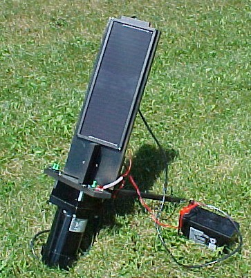
Here is a view of a small solar electric panel mounted directly to the shaft of a large DC motor for tracking. The solar panel charges a 12 VDC battery. The solar tracker circuit is mounted on the back of the solar panel. The shadow block is visible below the solar panel. Note how the 2 photocells are mounted on opposite sides of the shadow block's central divider.