MTM Scientific, Inc. : How to Rewind an Alternator Stator
The basic Automotive Alternator is a surprisingly adaptable generator of electricity. Windmill projects often use auto alternators because of their ready availability, low cost, and rugged mechanical construction. Unfortunately, standard alternators generally require high RPM to produce 12 VDC power. One possibility for increasing low RPM voltage output is installing a higher voltage stator, as described in our Alternator Booklet. Such a modification will approximately double the output voltage for a given RPM.
Substantially higher output voltages can be achieved by winding a "special purpose" stator. Hand winding a stator is not especially difficult, and it only requires a few hours of effort.
What follows is a brief description of a basic stator winding project, with some useful hints, tips, and performance data.
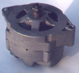
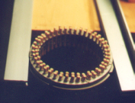
The Alternator: We begin with a Delco-Remy automotive alternator. This particular model is the 10-DN, which uses an external voltage regulator. This alternator was used on GM vehicles in the 60's and 70's. The alternator disassembles fairly easily, and the stator (as shown) is simply removed.
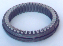
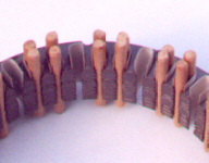
It is possible to remove the copper wire from the existing stator, and rewind the same core. However, re-manufactured bare cores are available for this alternator stator, and make the process much easier. Notice the paper insulation in the winding slots. The slot insulation should be tacked-in-place using 5 minute epoxy. To simplify winding it is helpful to install 3/16" diameter wooden pegs (1.5" long) into the slots as shown. The pegs create an excellent winding form for guiding the wire. The pegs are subsequently removed for winding the second, and third, phases.
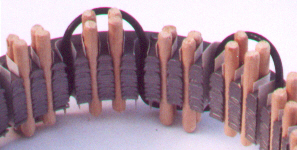
Support the stator core horizontally, at about table height, providing free access to the top and bottom. The raised ridges on the stator core help with jigging. The first phase winding takes the serpentine path shown by the black (oversized) wire. This is called a wave winding. Carefully examine the original stator windings and duplicate their size, location and general shape... Otherwise the new stator may not fit in the housing!
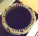
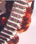
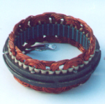
It is important to reserve space for the next two phases. The photo shows a typical first phase winding (pegs removed). The second and third phase windings are identical, except they are shifted over by one slot each. After winding, the coils can be secured in place with 5 minute epoxy. The slots are filled with silicone sealant to provide mechanical support and electrical insulation. The 3 starting leads are soldered together. The 3 end leads are fitted with ring eyelets, for attachment inside the alternator housing. This is called a "WYE" configuration.
End Results: In this example the stator was wound with 81 ft of 22 gauge copper wire per phase. When loaded in the test stand the alternator generated 12 VDC at 360 RPM, with full field excitation. This is a considerable improvement, considering a standard stator core requires about 1000 RPM.
SORRY: THIS ITEM HAS SOLD OUT
MTM Scientific, Inc.... Bare Stator Core
This Bare Stator Core is ideal for experiments rewinding automotive alternators. This core fits the standard Delco-Remy alternator used by GM in vehicles of the 60's and 70's. (Generally referred to as the 10-DN or 10-SI alternators... The most popular alternator ever built.) The Stator Core includes the paper slot insulation. Condition is pristine. Rewinding an alternator stator is not difficult, and it opens up a world of design possibilities for your project. Please note that our price includes shipping.
BARE STATOR CORE (CAT # BSC)...................................$XX.XX Postage Paid
SORRY: THIS ITEM HAS SOLD OUT