Hydrogen Line Radio Astronomy Experiments

M. Mruzek, Michigan USA

Helical Antenna for 1420 MHZ

Figure 1: Helical Antenna for Radio Astronomy at 1420 MHZ


This page describes radio astronomy experiments to observe stellar hydrogen line signals at 1420 MHZ. These experiments were performed in the summer of 2023 near Macon, Michigan USA. (42N, -84W). The initial goal was to detect the hydrogen line of several well known sources.  The project continued with sky mapping at the same frequency using a 3 meter (10 foot) TVRO parabolic antenna in drift scan mode. The observations began by using a simple helical antenna wound for 1420 MHZ, as shown in Figure 1. The helical antenna was found to be quite suitable and responsive when using the signal processing flow shown in Figure 2.


Radio Telescope Equipment Setup

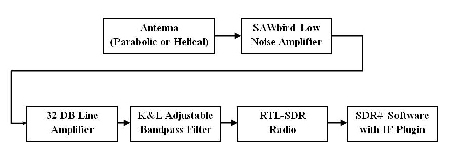
Figure 2: Radio Telescope Equipment Setup

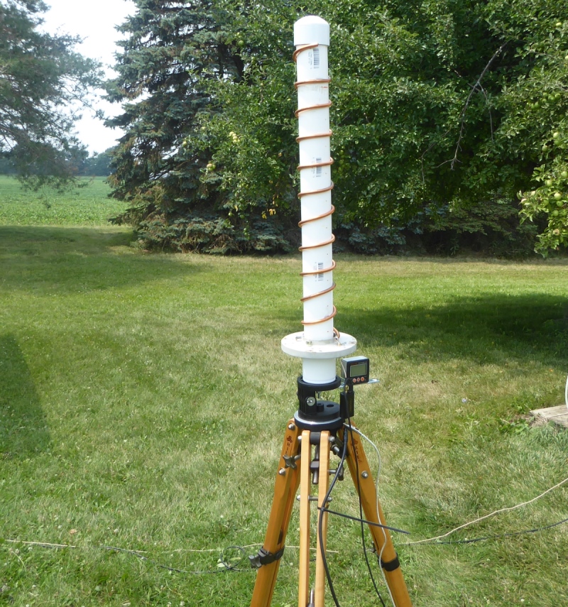
The helical antenna for 1420 MHZ was designed using a helical antenna calculator. (See link below)  Multiple experiments in the configuration of the helical antenna were made: including number of turns, reflector shape and impedance matching.  We found a 10 Turn Helical wound with 1/4" diameter soft copper tubing on a nominal 2" schedule 40 PVC pipe worked very well. The final version of the reflector is a 6" diameter aluminum disk. The simplicity of the helical antenna combined with low fabrication costs and compact size make it an ideal first antenna for hydrogen line work. The primary reason for our transition to a parabolic TVRO satellite dish was because we already had the 3 meter dish in our backyard antenna farm.  
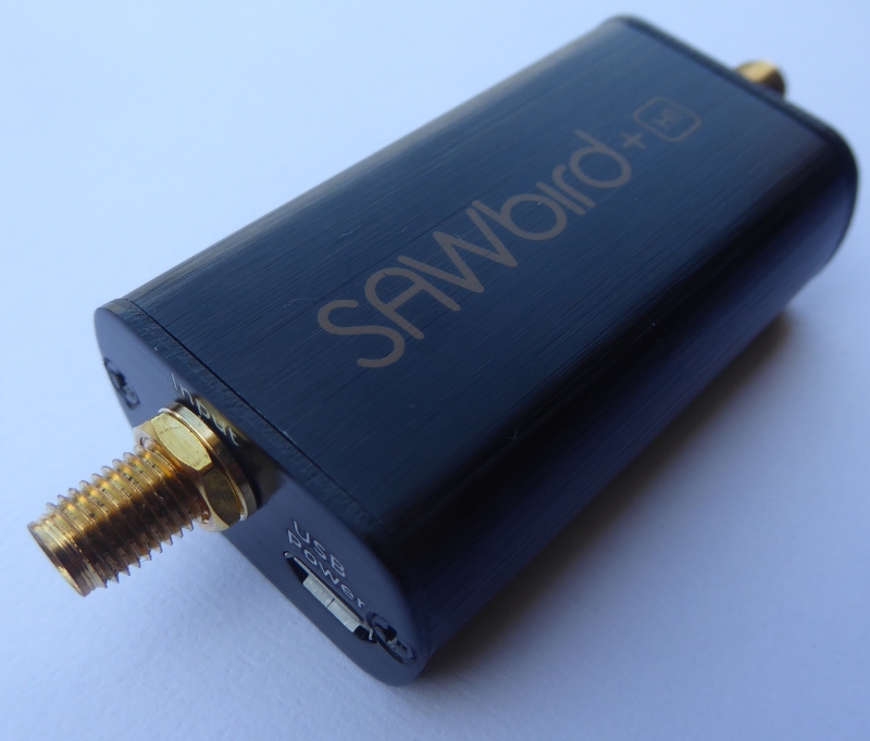
Low Noise Amplifier for Hydrogen Line Studies

Figure 3: SAWbird+ H1 Low Noise Amplifier for Hydrogen Line at 1420 MHZ

The most important amplifer in a radio astronomy telescope is the low noise amplifier (LNA) located at the mast of the receiving antenna. It is the LNA that most often establishes the noise figure of the amplifier chain. We experimented with several different LNA designs, including homebuilt and commercial.  We found the SAWbird+ H1 amplifier to work very well, and it is a relative bargain from Amazon at about $45.  We mounted the LNA in a PVC enclosure at the dish feed horn. The cable run from the LNA to our observatory consisted of about 25 feet of coaxial cable.
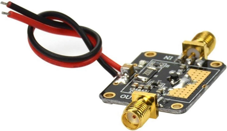

RF Line Amplifier Module

Figure 4: HUAZHU Broadband RF Line Amplifier Module

The coaxial cable run to the observatory terminated in a broadband RF Line Amplifier Module.  The HUAZHU module is advertised to provide 32 dB of gain. We mounted the line amplifer inside a die cast aluminum enclosure to minimize extraneous RF noise. These amplifers are available on Amazon for about $15.
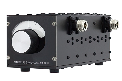

K & L Tunable Bandpass Filter

Figure 5: K&L Tunable Bandpass Filter

The output from the line amplifier is routed to a tunable bandpass filter set for 1420 MHZ. We are using the bandpass filter in our amplifier chain primarily because we have it available in our observatory. We eventually plan to test removal of the filter to gauge impact (after we complete our sky mapping project). We suspect it is not critical to performance, an important consideration since the list price of a new bandpass filter of this type is over $3000.
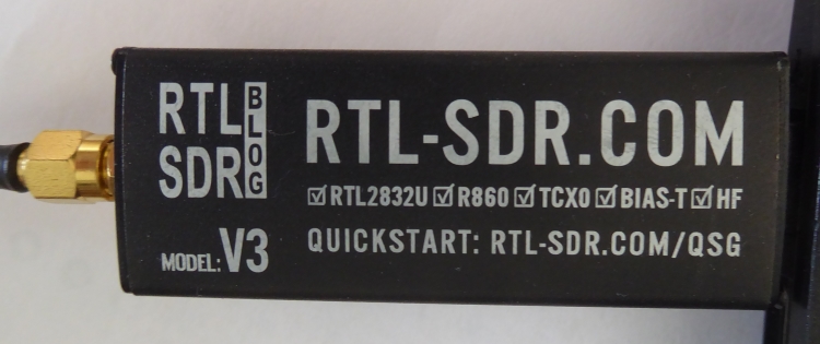
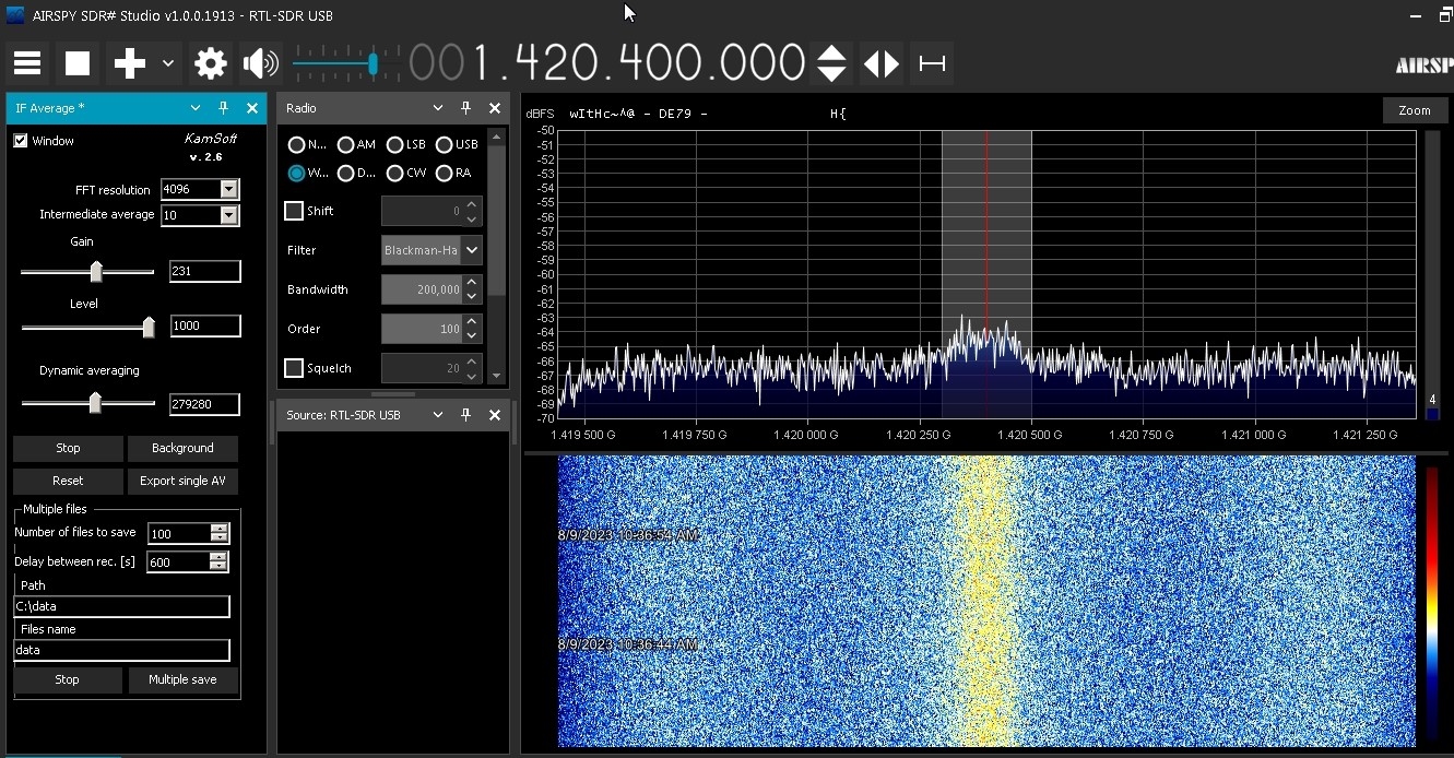
Software Defined Radio

Figure 6: RTL-SDR Software Defined Radio

We are using the RTL-SDR software defined radio. The SDR can be characterized as inexpensive ( $34 on Amazon) and well-supported by various software packages, including SDR# from AIRSPY, and GNU Radio derivatives for radio astronomy such as VIRGO.


Feed horn on 10 foot satellite dish

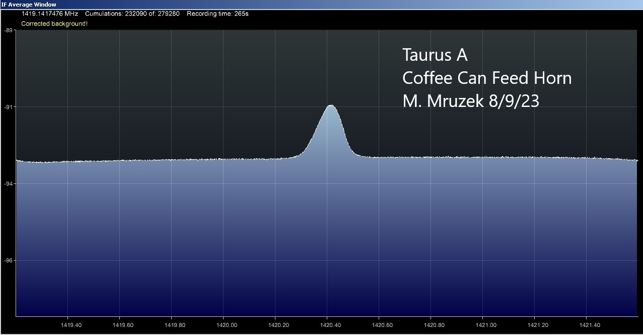
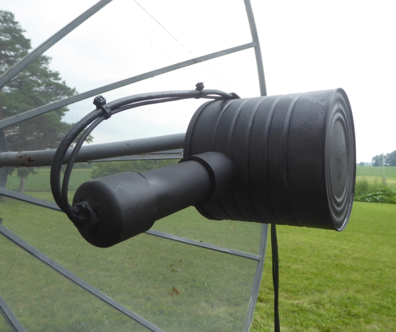
Figure 7: Feed horn and LNA on the 3 meter satellite dish

Transitioning from a helical antenna to the dish antenna created a need for a feed horn. Fortunately the hydrogen line frequency is relatively close to the same frequencies radio amateurs use for EME communication (Earth-Moon-Earth). We found a useful construction article for building a feed horn from a 3# coffee can. At first this sounds almost ridiculous, but the approach actually works surprisingly well. (See the article link below.)
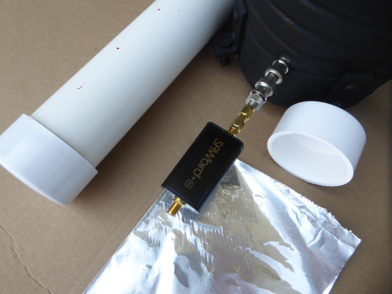

Details of LNA attachment and enclosure

Figure 8: LNA at feed horn in PVC enclosure with aluminum foil shielding

The main challenge with mounting the LNA at the feed horn of the dish was creating a weatherproof enclosure. We opted to place the LNA inside a PVC pipe enclosure attached with silicone sealant to the side of the coffee can.  The LNA was wrapped in aluminum foil to minimize RF interference. The +5VDC power was provided to the LNA by a micro-usb connector and cable. Note: The output signal of the LNA has a +5V DC component, which was OK in our setup because the line amplifier has I/O blocking capacitors.


Taurus A Waterfall

Figure 9: Spectrum and Waterfall for Taurus A

The software we use for general purpose observation of hydrogen lines at 1420 MHZ is SDR# from AIRSPY. The spectrum and waterfall display in SDR# will indicate the presence of a strong source, as shown in Figure 9. The manufacturer of the SDR dongle (RTL-SDR.COM) maintains an excellent set of webpages about the device, with many pages devoted to radio astronomy projects. There is also a forum that can provide assistance, as needed.

IF Average display for Taurus A

Figure 10: Taurus A IF Average Display

The SDR# software is excellent.  The authors of the software welcome the development of plugins to enhance functionality. One such plugin is specifically for doing radio astronomy. The IF Average Plugin allows for averaging of the IF signal to remove noise. The plugin also allows background noise subtraction, data storage and data acquisition scheduling.  Unbelievably, all this software is free!

We completed a sky map at 1420 MHZ using the 3M Satellite TVRO dish on 8/30/2023. We drift-scanned declinations from +22 to -28 degrees. This represents the range of movement possible when the dish is aligned North-South.  Each rectangle in the sky map represents a region of 5 degrees height, by 1 hour angle width. Inside each rectangle is a number representing the magnitude of the observed hydrogen peak height on the display screen, as measured using a ruler with millimeter units. The readings were placed in an Excel spreadsheet, with the cells conditionally formatted such that the brightness corresponds to the cell's numerical entry.

Sky Map at 1420 MHZ using 3M TVRO Dish

Figure 11: Sky Map at 1420 MHZ using 3M Satellite Dish


The sky map results show the general outline of our galaxy.  Taurus A is visible near the top left, and the galactic center is visible near the bottom right.  The bright spot near the bottom left is unknown, although we note that the dish is pointing very close to the horizon at those declinations.

Figure 12 is a view of the transit of the region near the galactic center using IF Average plugin for SDR#. Figure 13 is another view of the transit using H-Line software on a Linux machine.

Transit of region near Galactic Center

Figure 12: Transit of the region near the Galactic Center

Transit of Galactic Center

Figure 13: Transit of the region near the Galactic Center

References:

Radio Astronomy, 2nd Edition by John D. Kraus (CALL W8JK), published by Cygnus-Quasar Books, 1986.

Radio Astronomy Handbook, 4th Edition by Robert M. Sickels, published by Bob's Electronic Service, 1992-1993.

The Satellite Experimenter's Handbook, 2nd Edition by Martin Davidoff (CALL K2UBC), published by ARRL, 1990.

Hardware & Suppliers:

Link to the SAWbird+ H1 low noise amplifier from NOOELEC: Low Noise Amplifier

Link to the K&L Tunable Bandpass Filter (Pasternack): Filter

Websites:

Article describing construction of coffee can feed horns for L Band: Feed Horns

Information from SETI LEAGUE on feed horns for Hydrogen Line Astronomy: Feed Horns (Additional Information)

Helical Antenna Design Calculator: Helical Antennas

SDR# from AIRSPY (Software to operate the SDR dongle): SDR#

IF Average Plugin for SDR# (Ideal for Radio Astronomy Observations): IF Average Plugin