GPS
Solar Tracker (2)
MTM
Scientific, Inc.
This series of webpages describes a GPS enabled
solar
tracker based upon the STMAX tilt-tilt platform design. The STMAX solar
tracker controller is
described in much more detail in our book "Build a Solar Tracker"
and at
http://www.mtmscientific.com/stmax.html.
The first webpage ( Page 1: GPS Data Acquisition
) of this series described how to acquire time and
position data from a GPS module. This webpage describes how
to use the acquired GPS information to calculate the position of the
sun in the
sky. Our final webpage on this topic describes how to use the MEMS
ADC
counts to aim the tracker: ( Page 3:How to Aim
) The
calculation method used here is an adaptation of a software
program written by David Williams. The original program was
written
for generic BASIC, and calculates the Elevation and Azimuth of
the sun based upon the observer's position and time. We find it quite
remarkable that such a relatively simple program is able to perform
this calculation so well. Here is the original program souce code from
David Williams: sunalign.bas
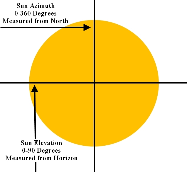 Figure 1. Definition of
Elevation and Azimuth
Figure 1. Definition of
Elevation and Azimuth
You can run the original program using many different versions
of
BASIC, for example Microsoft's QuickBASIC Version 4.50. The original
program is interactive, and will ask for the time, date and location
coordinates
it needs. We suggest that you familiarize yourself with the original
program to
gain a basic understanding of how it works.
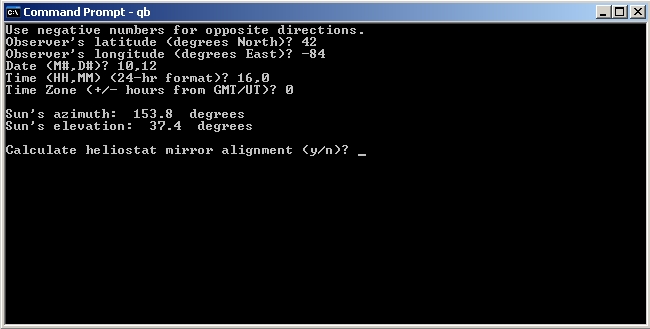 Figure 2.
Screenshot showing original program being used in QuickBASIC
Figure 2.
Screenshot showing original program being used in QuickBASIC
There are several substantial programming challenges involved in
adapting the original program to Picaxe BASIC language, as used by
the
Picaxe-20X2 microcontroller. The main challenges are: 1) Picaxe BASIC
performs all math calculations using only positive single or double
byte integers, 2) The Picaxe
BASIC trigonometric functions use units of degrees (instead of
radians), and 3) The devices using Picaxe BASIC have limited
memory space for
variables and data. Given these limitations you might be surprised to
know this calculation is even possible using a Picaxe-20X2!
Since Picaxe BASIC only performs positive integer math, it is necessary
to write code with each variable assigned a bit flag to indicate the
sign.
Subsequent math operations use the flags in logical branches
for calculations. In essence we are creating a method to handle
negative
and positive integer numbers. The fact that we must perform math using
integers requires keeping the arithmetic range between 0 and 255 for a
byte variable, or 0 and 65535 for a word variable.
The limited memory space of devices used with Picaxe BASIC requires the
careful
assignment and use of variables. The single most important factor in
that regard is to use (and reuse) scratchpad variables as often as
possible during the calculations. We emphasize this is in the code by
often naming those variables as temporary.
Because negative integers are not allowed in Picaxe BASIC we use a
method of addition and substraction in several places in the code
called 'midpoint math'. Essentially this is a simple technique of
shifting the zero origin to the midpoint of a word variable integer
(32768).
We also found an opportunity to improve the accuracy of the Picaxe
BASIC sine function near a zero crossing. Picaxe BASIC uses a unique
coding system to indicate positive and negative trigonometric values,
refer to the manuals for more details. Improving the accuracy
of the trigonometric functions in general might be an opportunity
for future work.
The calculation of sun position also requires calculation of an entity
called the 'Equation of Time' (EOT). Essentially this is the offset in
minutes relating the sun's actual position relative to an average
theoretical position. We have modified the original code to use a
different method of calculating the EOT. See the comments in the code
for a web reference.
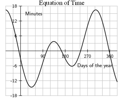
Figure 3. Graph of
Equation of Time (EOT)
This code can be easily tested using the simulation mode of the Picaxe
Programming Editor. (You don't even need a Picaxe-20X2 chip!) We've
done
some basic testing of the code for different times, dates and
locations. You may want to do more testing for your location. The setup
parameters for the input variables are assigned at
the start of the code, and can easily be changed as desired.
Here is the complete circuit diagram for the GPS Solar Tracker. You
will see we added two optional features: 1) An LED that illumates at
Solar Noon (i.e. Azimuth = 180). We also added a digital I/O for a
switch, which can be used to detect wind gusts or for any other purpose
you may desire. This design builds nicely on all of our previous solar
tracker kits. If you study the software listing, you will also see that
we added a Heliostat feature in the code. This was fairly easy to do,
and it uses the same method given in the original code as written by
David Williams.
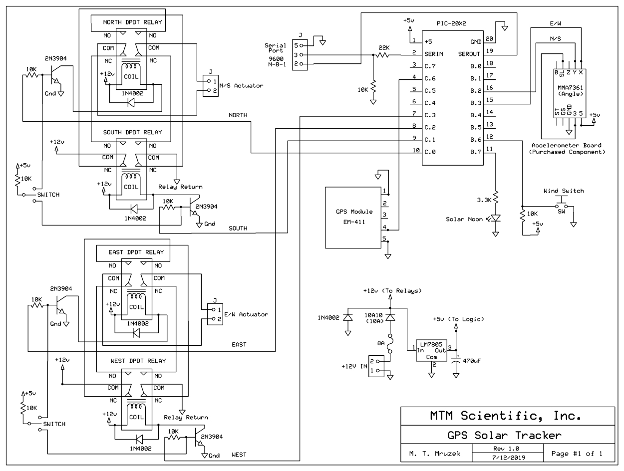 Figure 4. Circuit Diagram of GPS Solar
Tracker
Figure 4. Circuit Diagram of GPS Solar
Tracker
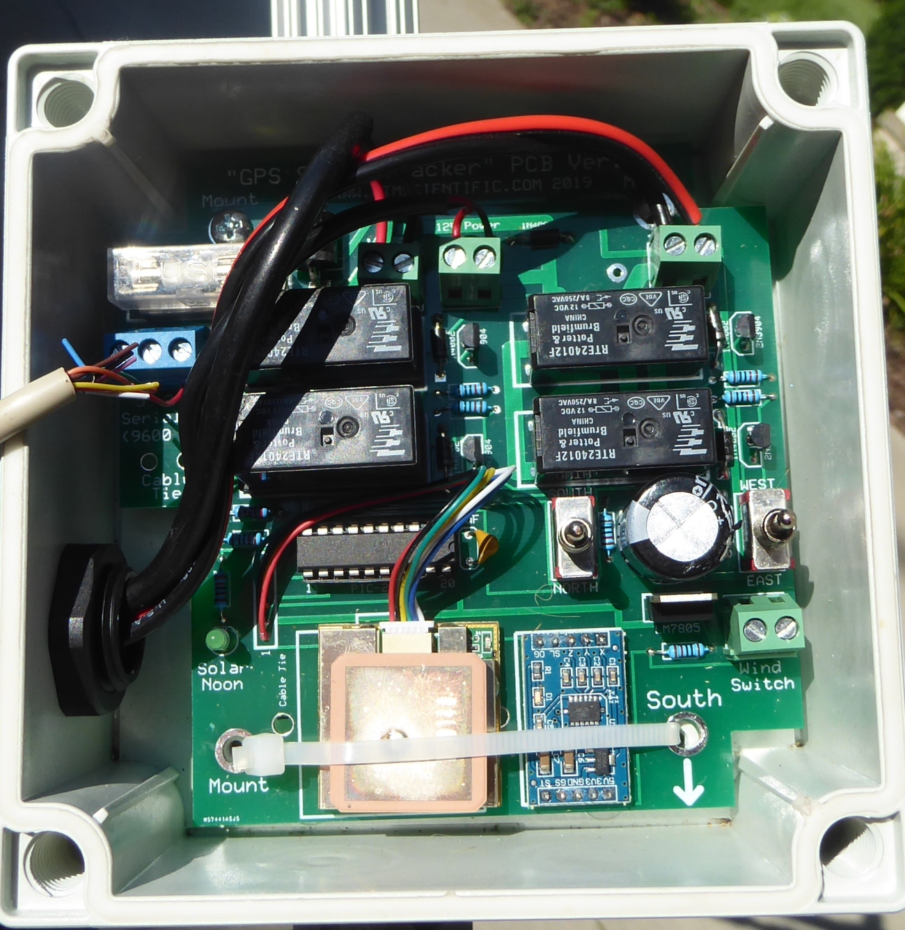
Figure 5. GPS Solar Tracker based on
STMAX
Here is the Picaxe BASIC code for calculating the position of the sun
in the sky based on the observer's location and time. This is the file
for download: sun_28.bas
As you can see in the
photo, we have designed a PCB for this project. We have some extra
PCB's from our prototype run, so if you are interested in duplicating
this projecet please write to us by email if you are interested in
purchasing one. This is a really fun project to experiment with!
You can populate this board using the parts from out STMAX kit, all you
need to add is the GPS module.
The STMAX series of solar trackers use a tilt-tilt platform mechanical
design, as detailed in our book. Most of the examples we have shown for
tilt-tilt platforms have used the 80-20 aluminum extrusion as the
structural element. There are other methods to design tilt-tilt
platforms. The photograph in Figure 6 shows a tilt-tilt platform build
using 2 gearmotors. The motors are arranged such that one motor does
the North-South motion, and the other motor does the East-West motion.
The motors were chose to have low RPM output. This type of motor is
called a gearhead motor. The GPS Solar Tracker controller rides on the
final output stage.
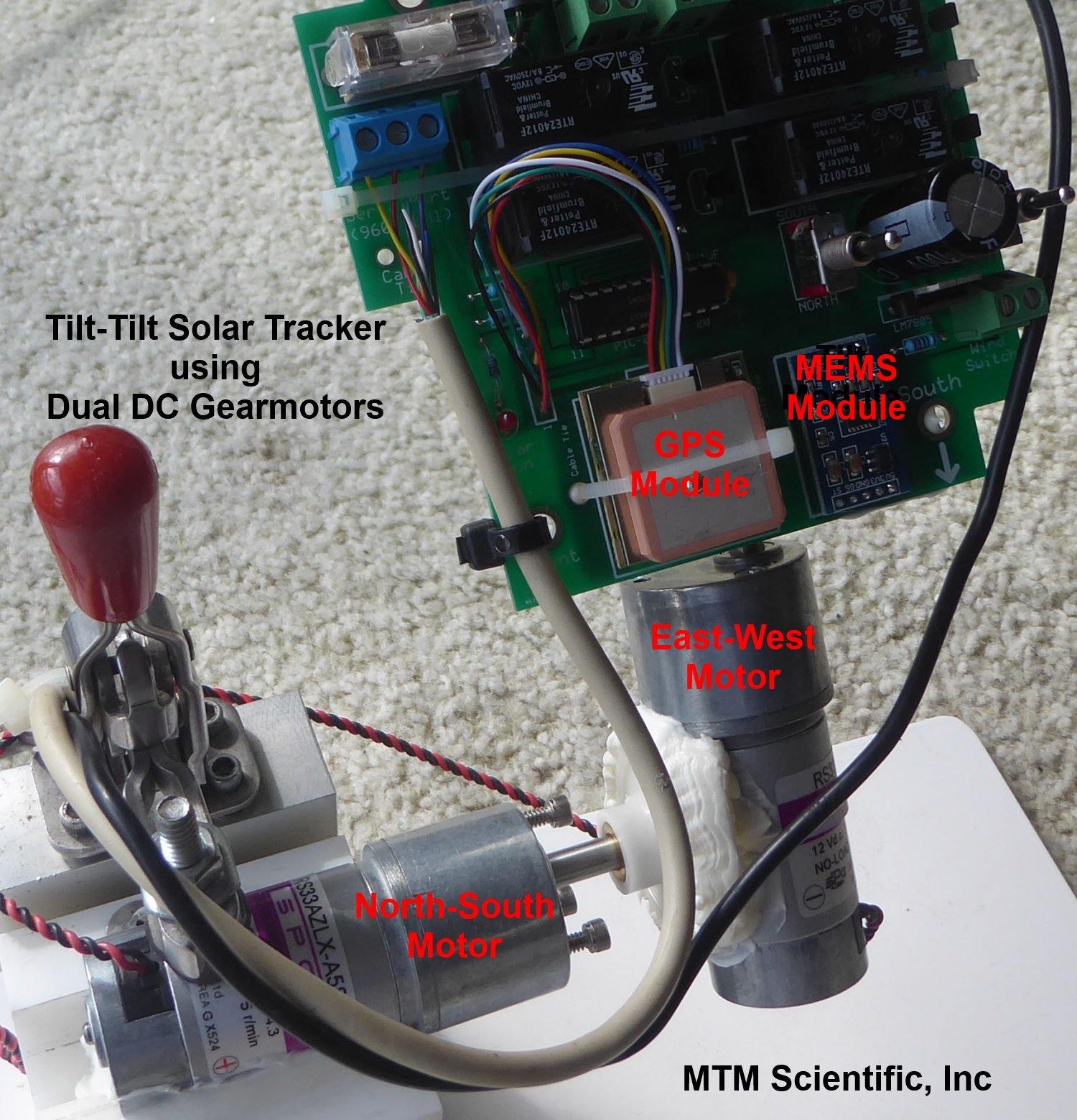 Figure 6.
Gearhead DC motors used to create a Tilt-Tilt platform
Figure 6.
Gearhead DC motors used to create a Tilt-Tilt platform