DIP Switch CMOS Programmer for MTM's CATV Tuner
The Television Tuner sold by MTM Scientific, Inc can be used to build several interesting projects, including an amateur Radio Telescope or a Wideband FM Receiver. In use, the tuner is programmed via a proprietary serial bit stream, commonly consisting of 27 bits. The bit stream programs the operating frequency and several other important tuner parameters. We have already described how a personal computer can be used to do the bit programming with software. Here we describe how to build a dedicated programmer for the tuner using 4000 series digital CMOS integrated circuits.
We have found a dedicated programmer is useful for several reasons. First, it removes the requirement to have the tuner connected to a personal computer. Computers tend to generate RF electrical interference, which can be especially bothersome when doing radio astronomy. Also, using a personal computer to program the tuner requires a computer operating system with direct control of the parallel port. This effectively means using Windows 95, Windows 3.1 or DOS, which can often be inconvenient.
Here is a link to the circuit diagram for the CMOS based programmer: Programmer Circuit Diagram. This file is in PDF format and requires the free Adobe Acrobat Reader software to view it. Note that the circuit diagram spans two pages.
The programmer is designed to generate a 27 bit code and send it to the tuner. Although the tuner can also be programmed with an 18 or 19 bit code, the 27 bit code is the most flexible. Individual bit states of high or low are set by a series of 4 DIP switchblocks, each containing 8 switches. The bit states are parallel-loaded into a series of 4 DIP shift registers with a trigger pulse. Subsequently, a series of 27 clock pulses shifts the data out of the registers and into the tuner. (Although 32 switches exist in this configuration, only 27 are actually meaningful to the tuner.)
The balance of the circuit is for: generating the trigger and clock signals, creating a high 'enable program' signal for the tuner, debouncing the power switch and counting to 27 (for sending 27 bits). In the circuit, all the timing signals are controlled by using resistors and capacitors in RC combinations, so don't make value substitutions.
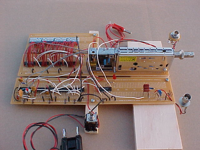
We found it most convenient to lay out the circuit construction on individual prototype breadboards, as shown in the picture. Notice that we used a toggle switch to control the main 5 VDC power, and a momentary switch to initiate the actual bit stream output. Also, the 'lock' signal from the tuner was run through 2 spare CMOS inverters to power a small LED. The LED glows when the tuner is locked.
The circuit diagram for the programmer lists a bit sequence useful for receiving 611 MHZ. This frequency is UHF TV station 37, which is protected for Radio Astronomy use. The details for changing the 27 bit sequence can be found in the datasheets for the tuner. However, we have found this can be quite challenging to decipher and have written a tutorial to explain the 27 bit sequence in more clearly. It is available here: 27 Bit Explanation
Two additional features were added to the programmer you see in the photo. The first is a headphone output jack for listening to audio from the tuner. This is helpful for identifying intereference, for example a local TV station on channel 36 or 38. The second feature is a diode detector identical to the circuit described on our Radio Telescope page. The output from this detector is the BNC connector, which is subsequently routed to a DC amplifier and the data recorder.
As interesting as this project is to construct, we'd like to suggest the possibility of an even easier method of programming the tuner... which is with a PIC controller. We are in the process of doing just that, and we will write a webpage describing the project soon.
Click Here to View other Products from MTM Scientific, Inc.